Microelectromechanical magnetometer

a magnetometer and micro-electromechanical technology, applied in the direction of magnet field measurement using permanent magnets, resistance/reactance/impedence, instruments, etc., can solve the problem of affecting the physical or electrical response of the magnetometer itself, affecting the accuracy of the magnetic field measurement, and requiring extensive and complex calibrations

Inactive Publication Date: 2007-04-19
LUCENT TECH INC
View PDF17 Cites 10 Cited by
  • Summary
  • Abstract
  • Description
  • Claims
  • Application Information

AI Technical Summary

Benefits of technology

[0006] To address one or more of the above-discussed deficiencies, one embodiment of the present invention is an apparatus. The apparatus comprises a substrate and a MEM device. The MEM device includes a comb capacitor and a magnetic element physically connected to on

Problems solved by technology

Existing apparatus are deficient in one or more of these desirable features.
Consequently, extensive and complex calibrations are needed to use these magnetometers.
In other instances, components of magnetometers can become distorted when moving in response to a change in the magnetic field, thereby altering the physical or electrical response of the magnetomete

Method used


Image

  • Microelectromechanical magnetometer
  • Microelectromechanical magnetometer
  • Microelectromechanical magnetometer

Examples


Embodiment Construction

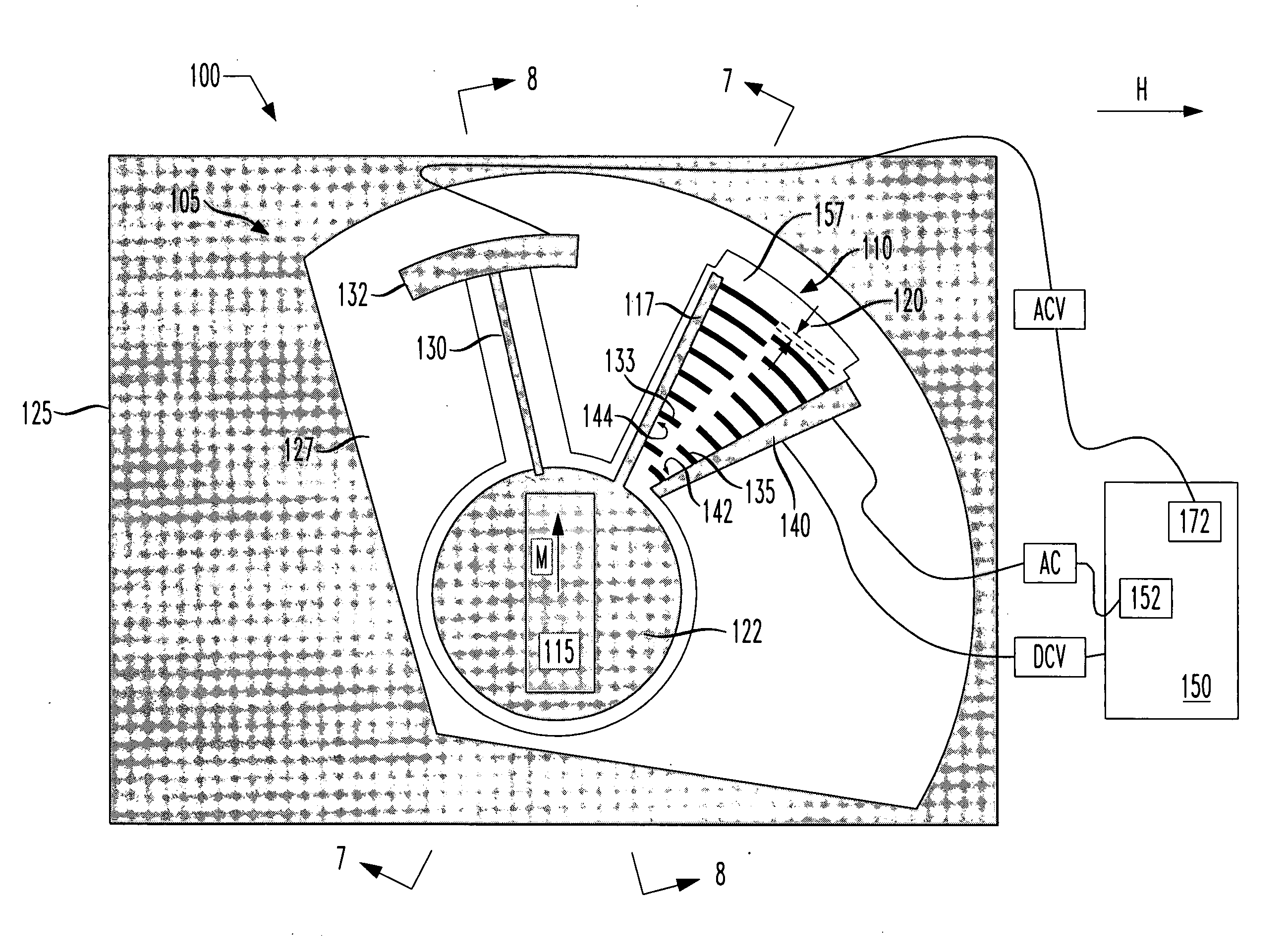
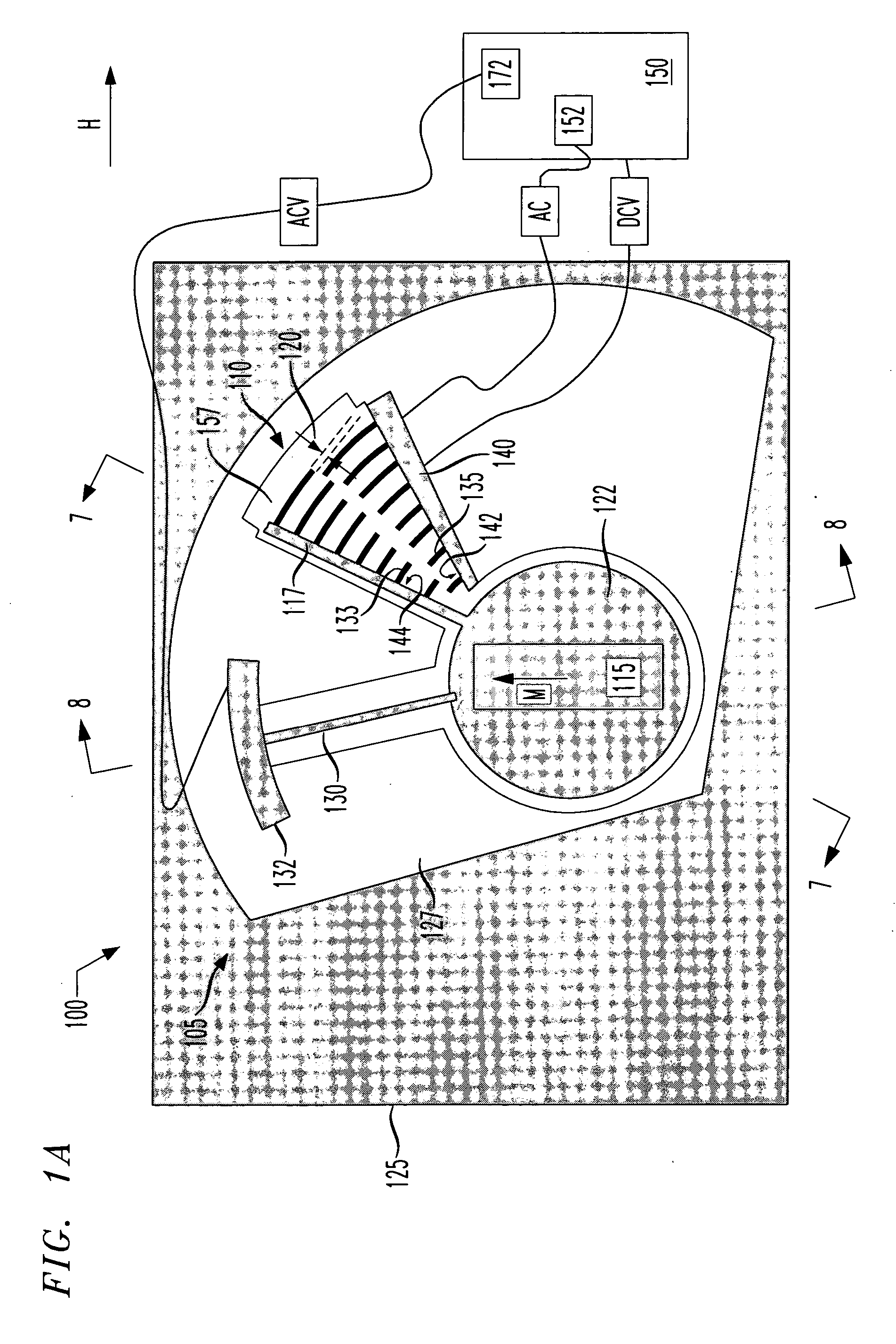
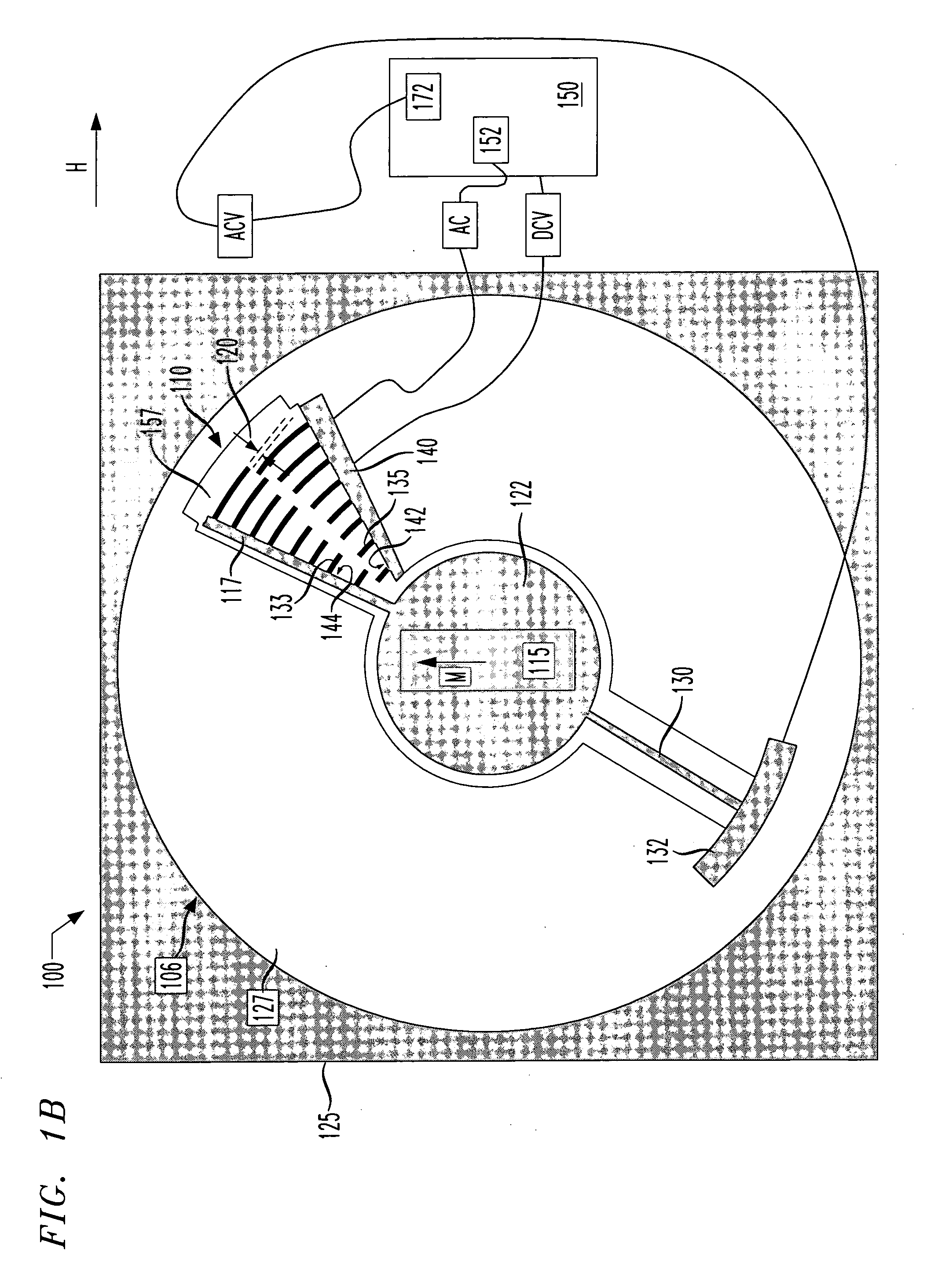
[0015] The various embodiments use MEM devices having comb capacitors to facilitate the measurement of magnetic field intensity and direction. The term comb capacitor as used herein is defined as a structure having at least two electrodes, wherein each electrode has a plurality of substantially parallel fingers projecting from opposing surfaces of the electrodes. The two electrodes are configured so that the fingers of one interdigitate with the fingers of the other electrode. Exemplary comb capacitor designs are presented in U.S. Pat. Nos. 6,667,823; 5,963,367; 6,122,961, 6,713,367; and 6,925,710, which are incorporated by reference herein in their entirety.

[0016]FIGS. 1A, 1B and 1C present a plan views of an exemplary embodiments of an apparatus 100 having different MEM devices 105, 106, 107. Turning to FIG. 1A, the apparatus 100 comprises a. MEM device 105. The MEM device 105 includes a comb capacitor 110, one or more spring elements 130, hub 122, and magnetic element 115. The m...


PUM


Abstract

An apparatus comprising a substrate and a MEM device. The MEM includes a comb capacitor and a magnetic element physically connected to one electrode of the comb capacitor. The magnetic element is capable of moving the one electrode in a manner that alters a capacitance of the comb capacitor. The apparatus also includes at least one spring physically connecting the magnetic element to the substrate.

Description

TECHNICAL FIELD OF THE INVENTION [0001] The present invention relates, in general, to devices for measuring magnetic fields, as well as methods of using and manufacturing such devices. BACKGROUND OF THE INVENTION [0002] The measurement of magnetic fields has many applications, such as navigation, metal detection in security settings, and oil and mineral prospecting. There is a long-standing need for inexpensive low-power apparatus to detect small changes in magnetic fields over large ranges. Existing apparatus are deficient in one or more of these desirable features. [0003] For example, certain microelectromechanical (MEM) magnetometers only measure changes in magnetic fields over a small range of intensity. Thus, multiple magnetometers, each adjusted to a different range of magnetic field, may be needed to cover a desired range. Also, some magnetometers respond nonlinearly to changes in the magnetic field intensity. Consequently, extensive and complex calibrations are needed to use...

Claims


Application Information

Patent Timeline
IPC IPC(8): G01R33/02
CPCG01R33/0286G01R33/038
Inventor BOLLE, CRISTIAN A.SIMON, MARIA E.
Owner LUCENT TECH INC
Why Eureka
Try Eureka