Electronic control system and method for an auxiliary device interlock safety system

a technology of electronic control system and auxiliary device, which is applied in the direction of loading/unloading vehicle arrangment, transportation items, refuse collection, etc., can solve the problems of lack of familiarity with the control sequence, lack of standardization in the control sequence and type of control, and general deficiency of auxiliary device control system to provide adequate level of safety to an auxiliary device user. , to achieve the effect of reducing auxiliary device operator error and enhancing the safety of a

Inactive Publication Date: 2007-04-19
BRAUN THE
View PDF16 Cites 34 Cited by
  • Summary
  • Abstract
  • Description
  • Claims
  • Application Information

AI Technical Summary

Benefits of technology

[0009] An electronic controller, control system and method for controlling the operation of a vehicle auxiliary device, such as a wheelchair lift installed in a vehicle, are provided. The control system includes an electronic controller with a microprocessor or the like that operates under software control to communicate with a vehicle's OEM controller and a plurality of sensors, which may be associated with OEM and auxiliary device subsystems. The auxiliary device controller processes the sensor communications to determine the occurrence of an unsafe condition, and prevents the operation of OEM and auxiliary device subsystems relative to the sensor communications to enhance the safety of a auxiliary device user. Additionally, the auxiliary device controller operates to coordinate various OEM and auxiliary device subsystems to reduce auxiliary device operator error.

Problems solved by technology

Unfortunately, such auxiliary device control systems have proven to be generally deficient in providing an adequate level of safety to an auxiliary device user.
Several factors have been identified which contribute to operator error: (1) the lack of familiarity with the controls, (2) the lack of standardization in the control sequence and types of controls (e.g., different controls for different lifts), and (3) the lack of operator training.
In addition, even though the user of the auxiliary device may be fully visible to the operator, the operator may not be aware of the passenger's presence.
This “looked but did not see” or daydreaming phenomenon is a frequent cause of motor vehicle collisions.
Additionally, lack of routine system maintenance has been cited as a cause of malfunctions of auxiliary devices.

Method used


Image

  • Electronic control system and method for an auxiliary device interlock safety system
  • Electronic control system and method for an auxiliary device interlock safety system
  • Electronic control system and method for an auxiliary device interlock safety system

Examples


Embodiment Construction

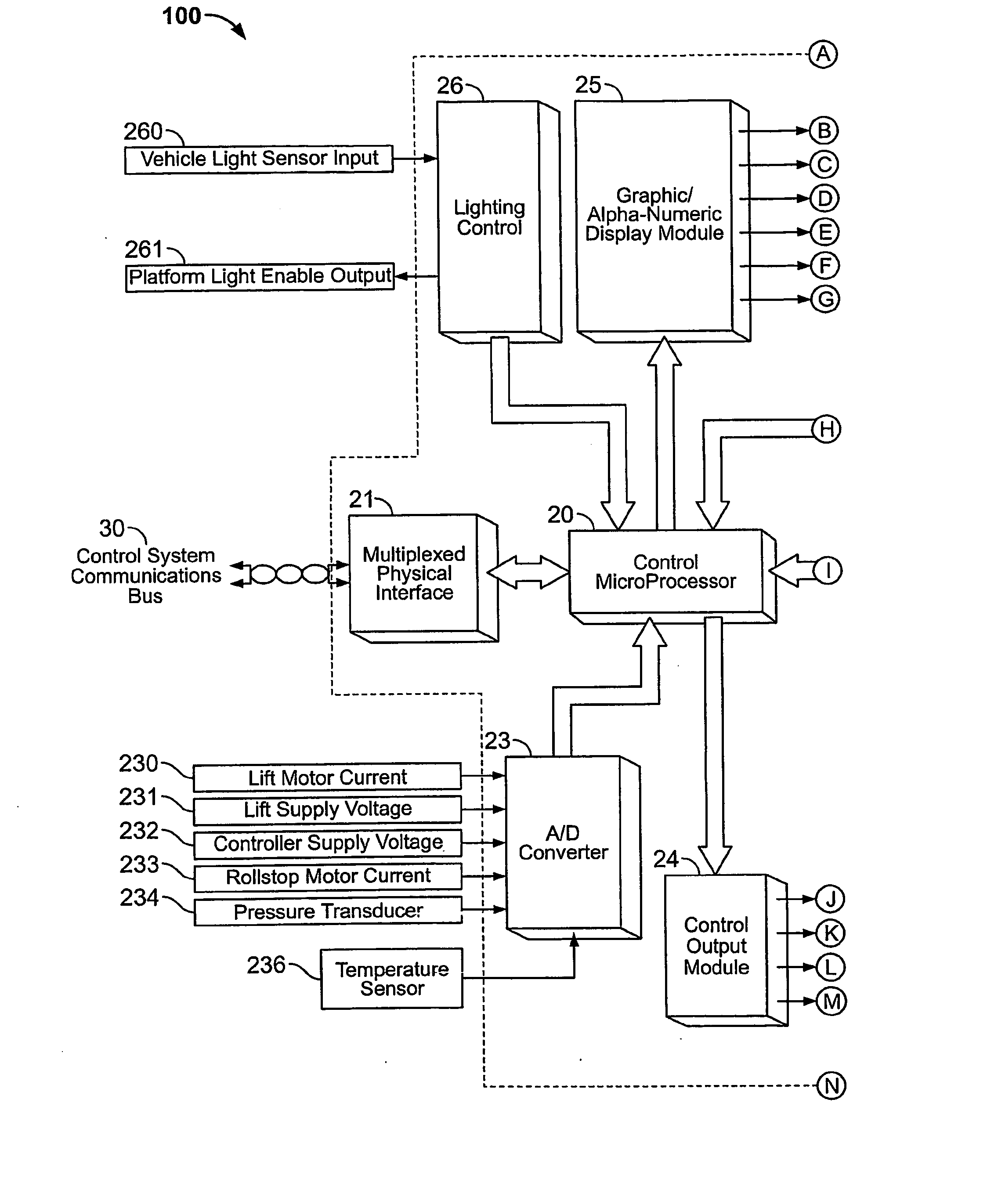
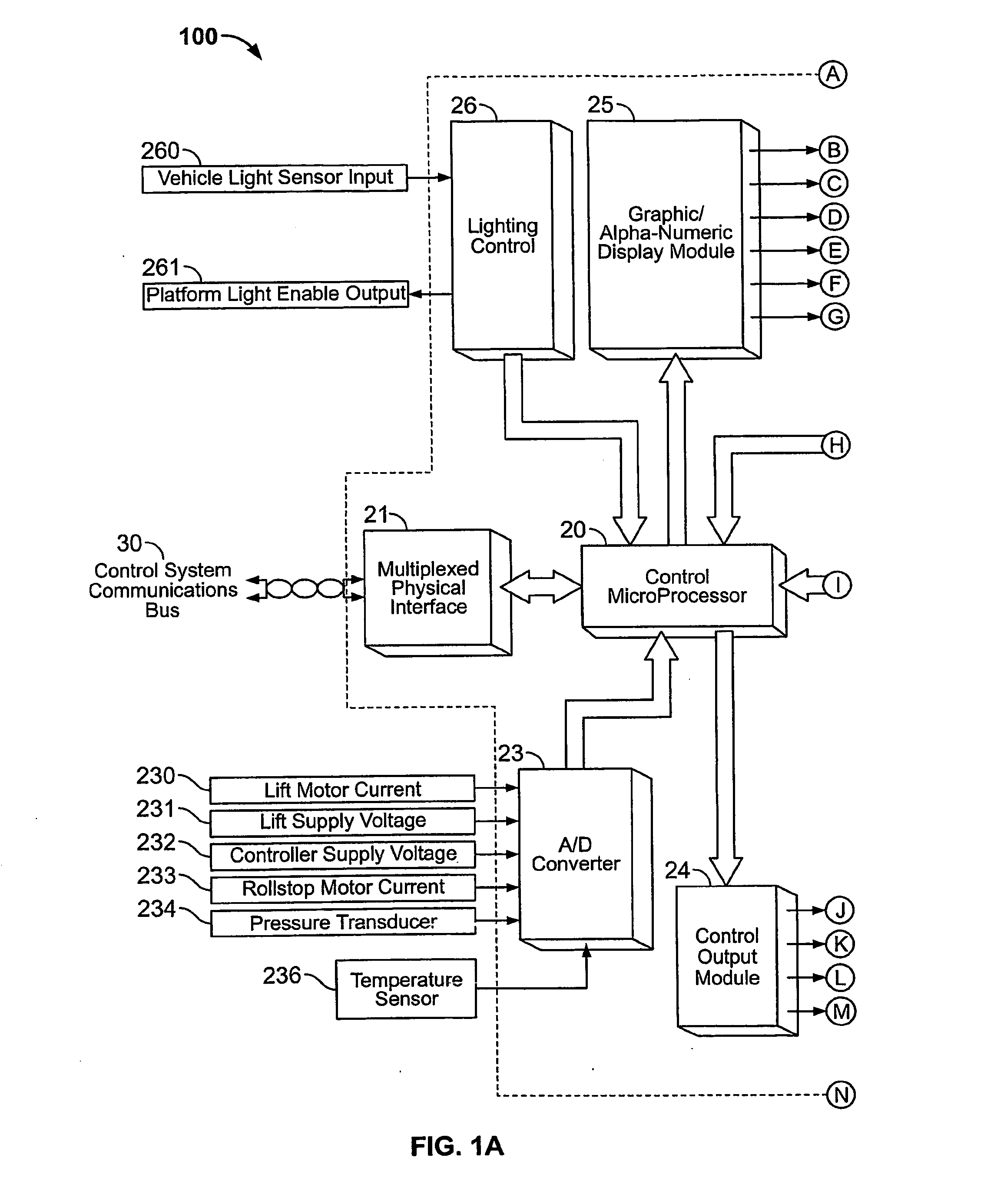
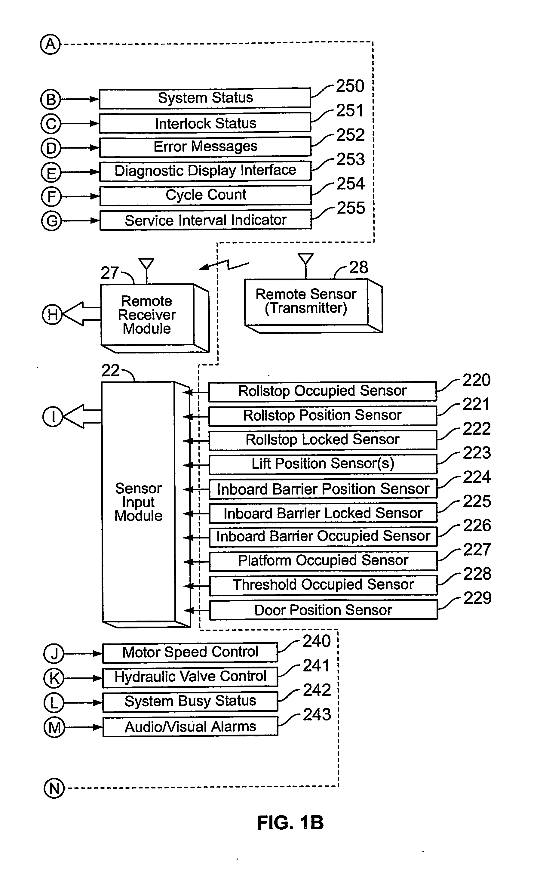
[0014] Referring now to the figures, and particularly FIG. 1, a control system for an auxiliary device is shown. The control system may include an after-market type controller 100 (i.e., not OEM equipment) that is provided with an auxiliary device such as a wheelchair lift or ramp for controlling the auxiliary device. One exemplary auxiliary device is illustrated in FIG. 2 as a vehicle wheelchair lift 10, but the auxiliary device may be a wheelchair ramp or other device that helps a mobility-challenged person enter and exit a vehicle, building or other structure. As shown in FIG. 2, by way of example, the wheelchair lift 10 is installed in vehicle V such as a bus, van, or other suitable vehicle. Wheelchair lift 10 is installed in a doorway D and is bolted or otherwise fixedly attached to the vehicle floor F. With reference to the axis shown in FIG. 2, a direction closest to or toward the vehicle V shall be referred to as inboard (IB), whereas the direction away from or farthest from...


PUM


Abstract

A controller, control system and method for controlling an auxiliary device comprising a wheelchair lift, ramp, or the like are provided. An exemplary embodiment of the auxiliary device controller is microprocessor-based and communicates with a vehicle's OEM controller for receiving a plurality of sensor inputs, which originate from OEM and auxiliary sensors, process the sensor inputs, and control various OEM and auxiliary systems relative to the sensor inputs to effect a number of safety interlocks. The controller may operate to coordinate various OEM and auxiliary subsystems to automate auxiliary device operation to reduce operator error.

Description

CROSS-REFERENCE TO RELATED PATENT APPLICATION [0001] This patent application is a continuation-in-part of copending U.S. patent application Ser. No. 10 / 142,712, filed May 10, 2002, now allowed, which is a continuation-in-part of International Patent Application No. PCT / US01 / 27102, filed Aug. 31, 2001, which claims the benefit of and priority to U.S. Provisional Patent Application No. 60 / 229,922, filed Sep. 1, 2000. This application also claims the benefit of and priority to U.S. Provisional Patent Application No. 60 / 520,848, filed Nov. 18, 2003.FIELD OF THE INVENTION [0002] The invention relates generally to an electronic control system. More particularly, the invention relates to an electronic control system for an auxiliary device, such as a wheelchair lift, with an interlock safety system. BACKGROUND OF THE INVENTION [0003] In the automotive field, the operation of major original equipment manufacturer (OEM) subsystems, such as the engine, emissions, transmission, and braking has...

Claims


Application Information

Patent Timeline
Patent Type & Authority Applications(United States)
IPC IPC(8): B60P1/00B65F3/00A61G3/06B60P1/43H02H7/085
CPCA61G3/061B60P1/43B60P1/4471H02H7/0851A61G3/062Y10S414/134A61G2203/38A61G2203/46
Inventor GOODRICH, RONALDHEIGL, KEITH
Owner BRAUN THE
Why Eureka
Try Eureka