
Acoustic system

a technology of acoustic system and speaker, which is applied in the direction of single subwoofer, electrical transducer, substation equipment, etc., can solve the problems of insufficient low-range audio sound output from difficulty in enlarge the diameter of cone paper in restricted size of the charging stand speaker, etc., to achieve richly expressive acoustic spa

Inactive Publication Date: 2007-04-19
SONY CORP
View PDF9 Cites 18 Cited by
  • Summary
  • Abstract
  • Description
  • Claims
  • Application Information

AI Technical Summary

Benefits of technology

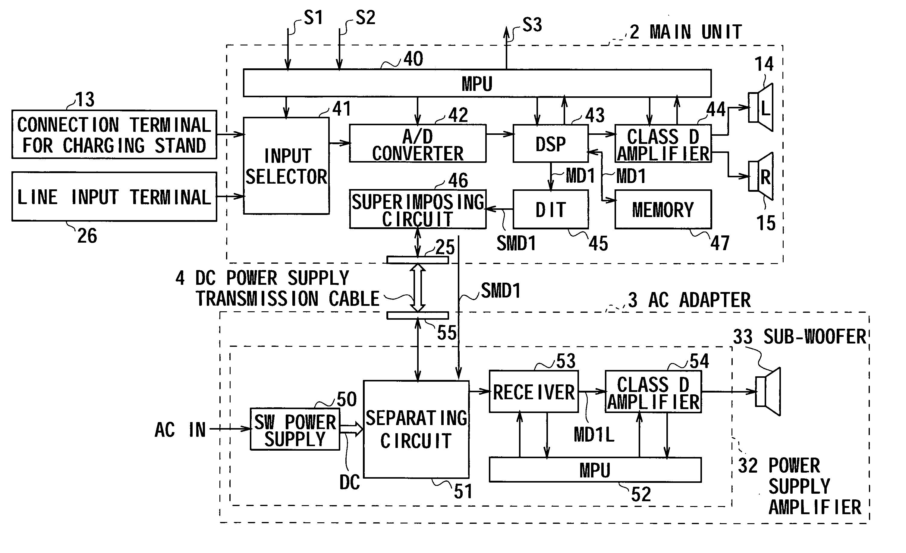
[0010] According to one embodiment of the present invention, in addition to output the mid-high range audio sound of the audio signal from the speaker units of the main unit, the present invention can output the low range audio sound of the audio signal transmitted from the main unit through the transmission cable can be outputted from the woofer unit of the AC adapter. Accordingly, the acoustic system which can provide a richly expressive acoustic space can be realized without enlarging the size of the main unit.

Problems solved by technology

However, in a portable telephone system of such a configuration, the size of the charging stand speaker is restricted in accordance with the miniaturization of the charging stand which mounts the portable telephone terminal.
For this reason, it has been difficult to enlarge the diameter of cone paper in the charging stand speaker.
Therefore, there is a problem that a low range audio sound outputted from the charging stand speaker is insufficient.

Method used


Image

  • Acoustic system
  • Acoustic system
  • Acoustic system

Examples


Embodiment Construction

[0019] Hereinafter, an embodiment of the present invention will be described in detail with reference to the drawings.

(1) Overall Structure of Acoustic System

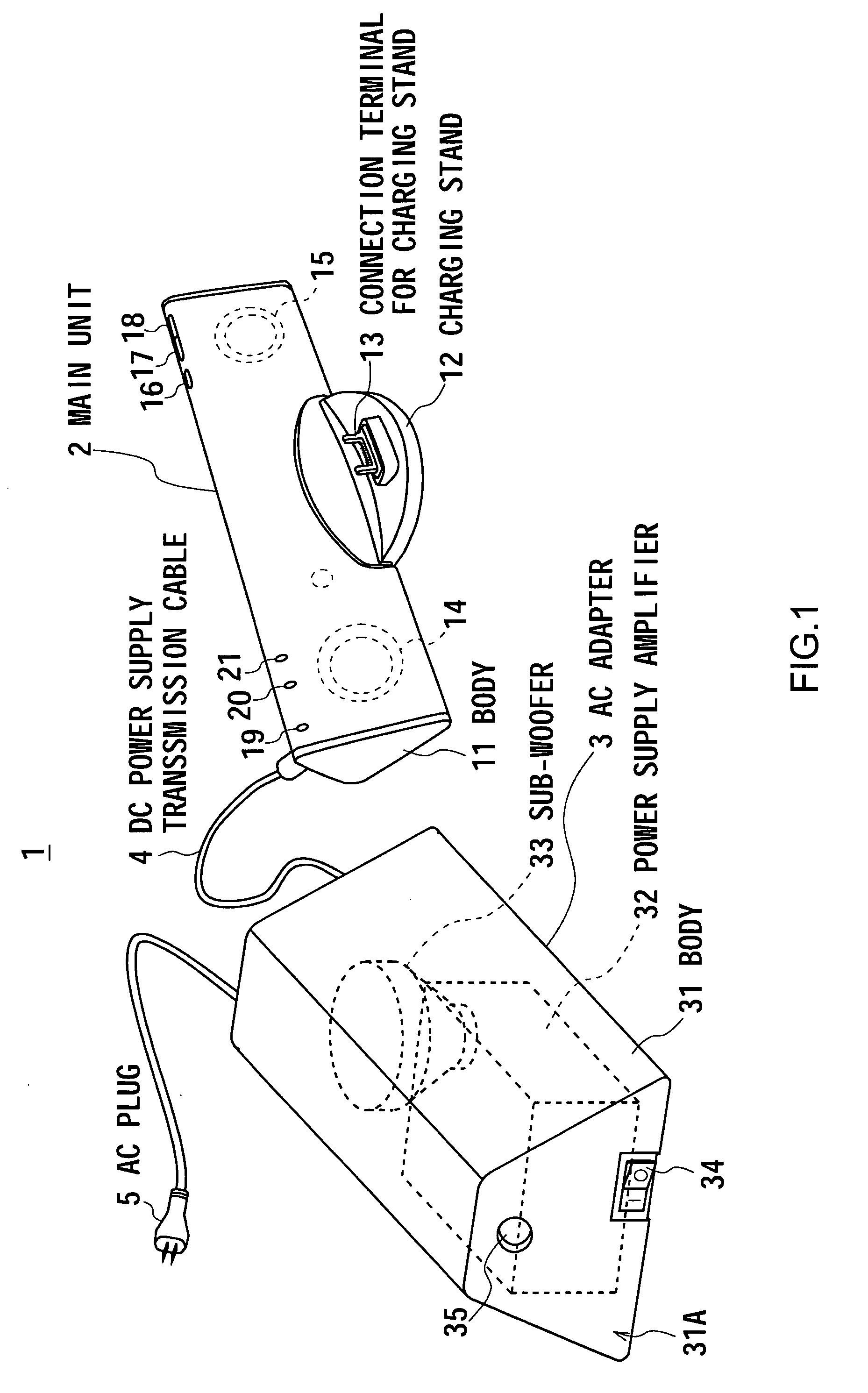
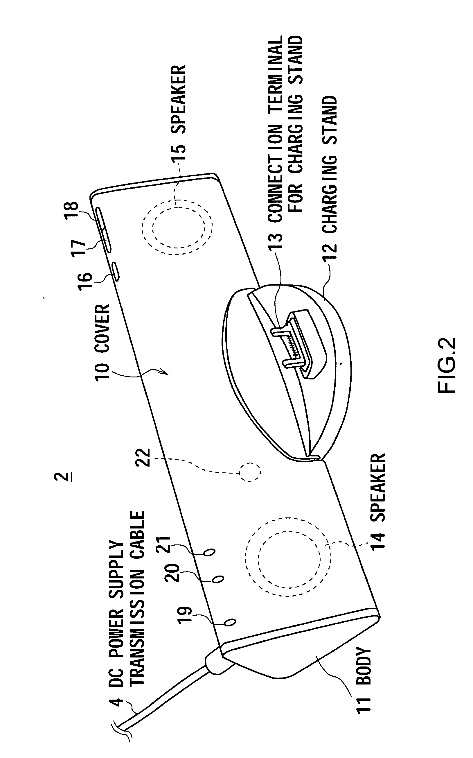
[0020] In FIG. 1, reference numeral 1 shows an acoustic system of 2.1 channel of the present invention as awhole. The acoustic system comprises a main unit 2 for charging a portable telephone with music reproducing function (to be described later), an Alternating Current (AC) adapter 3 for supplying a Direct Current (DC) power of predetermined voltage level to the main unit 2, and a DC power transmission cable 4 for connecting the main unit 2 and the AC adapter 3.

[0021] The AC adapter 3 is adapted to operate the main unit 2 by converting a voltage of AC100 V supplied from an AC plug 5 connected to a commercial AC power supply (not shown) into a voltage of DC12 V and supplying the DC power of the DC12 V to the main unit 2 through the DC power supply transmission cable 4. (2) External Structure of Main Unit

[0022] As shown in...


PUM


Abstract

In addition to output the mid-high range audio sound from the speakers of the main unit, the present invention can output the low range audio sound according to the audio signal transmitted from the main unit through the DC power supply transmission cable from the sub-woofer unit of the AC adapter. Accordingly, the present invention can provide a richly expressive acoustic space without enlarging the size of the main unit.

Description

CROSS REFERENCE TO RELATED APPLICATIONS [0001] The present invention contains subject matter related to Japanese Patent Application JP 2005-299188 filed in the Japanese Patent Office on Oct. 13, 2005, the entire contents of which being incorporated herein by reference. BACKGROUND OF THE INVENTION [0002] 1. Field of the Invention [0003] This invention relates to an acoustic system applicable to a portable telephone system which outputs music with high-quality reproduced from a portable telephone connected to, for example, a cradle. [0004] 2. Description of the Related Art [0005] A portable telephone system in which a portable telephone terminal is mounted on a charging stand as a main unit for charging through a charging terminal of the charging stand, and is adapted to output an audio sound obtained by reproducing music data by the portable telephone terminal from a speaker of charging stand built in the charging stand (forexample, refer to Jpn. Pat. Appln. Laid-Open Publication No....

Claims


Application Information

Patent Timeline
IPC IPC(8): H04B1/38
CPCH04R5/02H04R2205/021H04R2205/026H04R2499/11
Inventor YAMAMOTO, YOSHINORIMORIYA, AKIHITOSATO, YUTAKATAKAHASHI, OSAMUTAKAHASHI, TOSHIMASA
Owner SONY CORP
Learn More