
System and method for reduction of rebuild time in raid systems through implementation of striped hot spare drives

Inactive Publication Date: 2007-04-19
LSI CORPORATION
View PDF3 Cites 46 Cited by
  • Summary
  • Abstract
  • Description
  • Claims
  • Application Information

AI Technical Summary

Benefits of technology

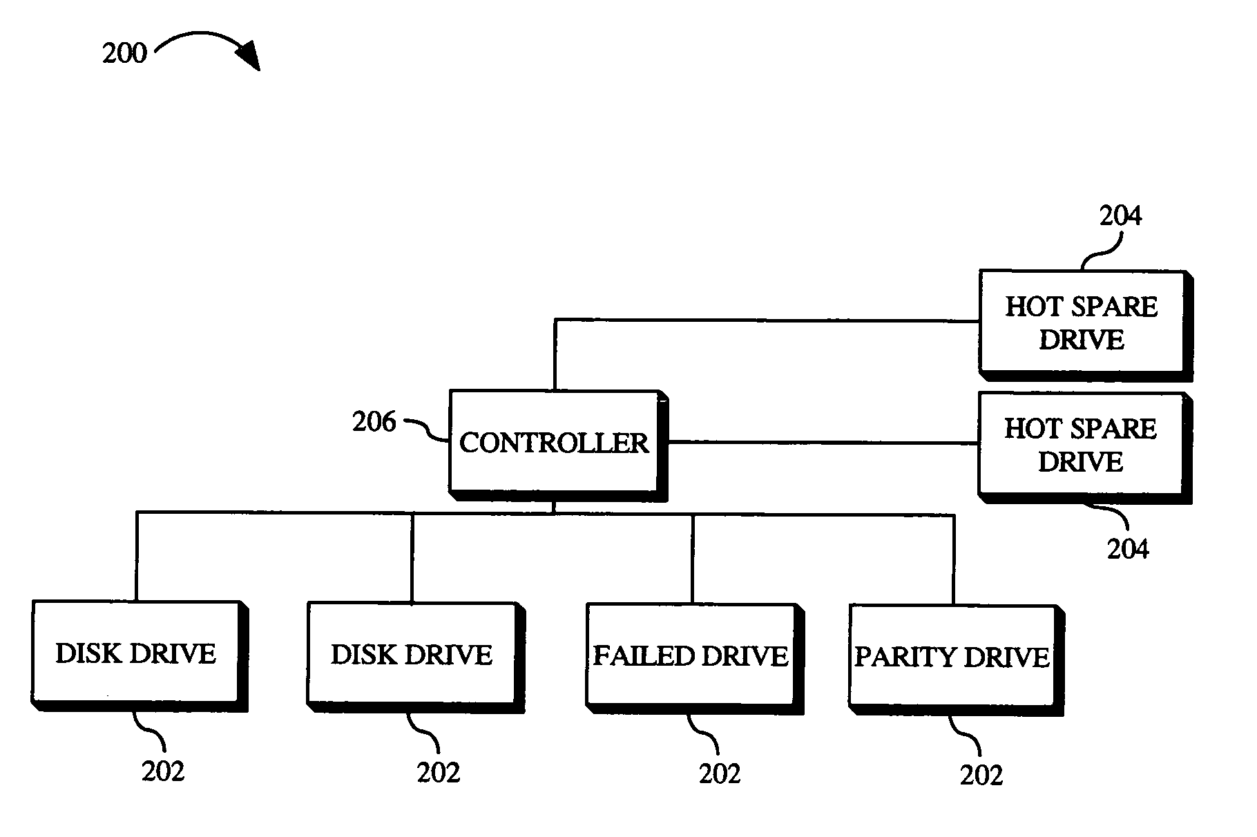
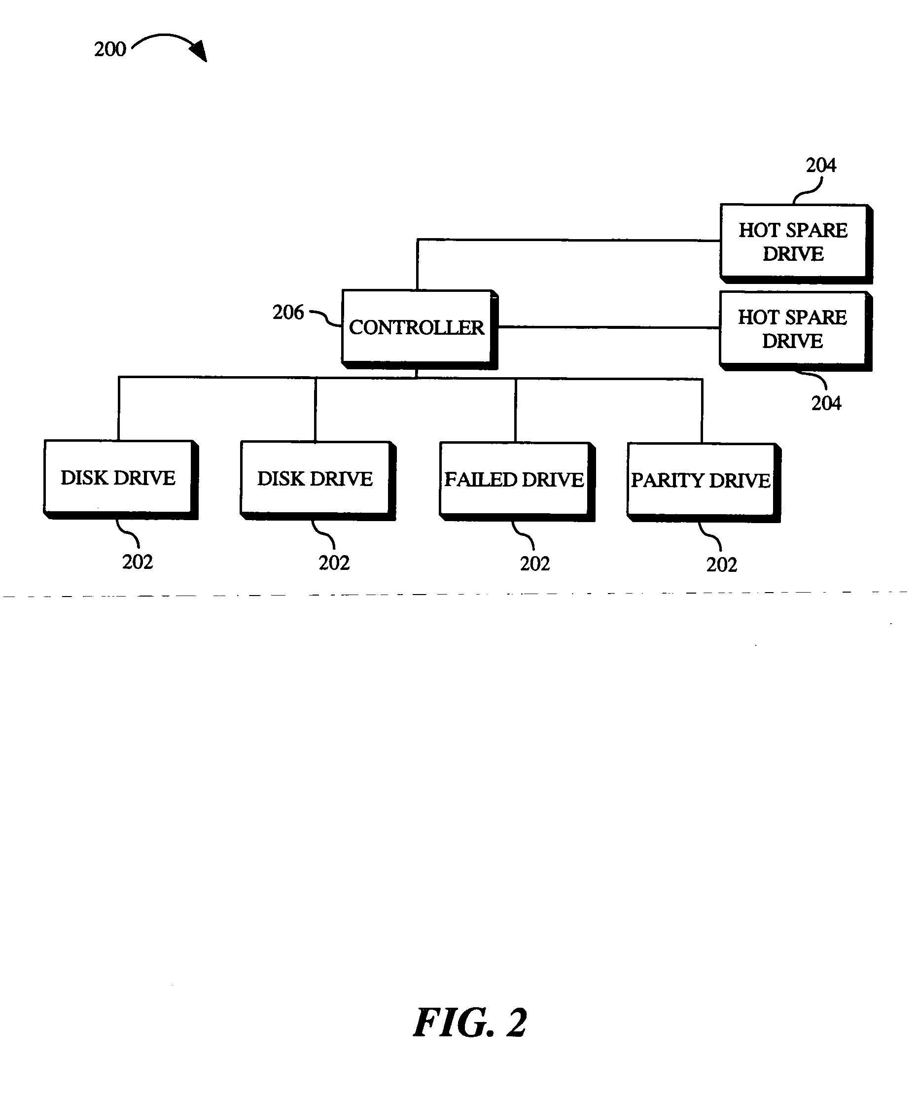
[0005] Accordingly, an embodiment of the present invention is directed to a system for reducing rebuild time in a RAID (Redundant Array of Independent Disks) configuration. The system includes a plurality of RAID disk drives, a plurality of hot spare disk drives, and a controller communicatively coupled to the plurality of RAID disk drives and the plurality of hot spare disk drives. The system functions so that rebuild data is striped by the controller across at least two hot spare disk drives included in the plurality of hot spare disk drives.
[0006] A further embodiment of the present invention is directed to a method for reducing rebuild time in a RAID (Redundant Array of Independent Disks) system. The method includes providing a plurality of hot spare disk drives; reconstructing data of a failed disk drive of the RAID system, the reconstructed data being rebuild data; and striping the rebuild data across at least two hot spare disk drives included in the plurality of hot spare disk drives.

Problems solved by technology

Because the rebuild data is being written to a single disk drive (the hot spare drive), the speed of the rebuild process is limited by the write performance of the hot spare drive and / or the bandwidth of the data path from the RAID controller to the hot spare drive.
With current systems, the rebuild process may take hours to complete.
This is problematic for a couple of reasons.
First, if a disk drive fails and the rebuild process is entered, the RAID array, although still functional, runs in a “degraded” mode for the duration of the rebuild process.
This means that the RAID array, due to the failure of the failed disk drive is not operating at peak efficiency or performance during the rebuild process.
Further, the RAID array is especially vulnerable during the rebuild process, because, if a second disk drive fails during the rebuild process, the RAID array may be unable to function.
Consequently, the RAID controller may be unable to rebuild the data of the failed drives, resulting in the data on the failed drives being lost.
However, the current solutions are typically not cost-effective and still produce less than desirable results.

Method used


Image

  • System and method for reduction of rebuild time in raid systems through implementation of striped hot spare drives
  • System and method for reduction of rebuild time in raid systems through implementation of striped hot spare drives
  • System and method for reduction of rebuild time in raid systems through implementation of striped hot spare drives

Examples


Embodiment Construction

[0013] Reference will now be made in detail to the presently preferred embodiments of the invention, examples of which are illustrated in the accompanying drawings.

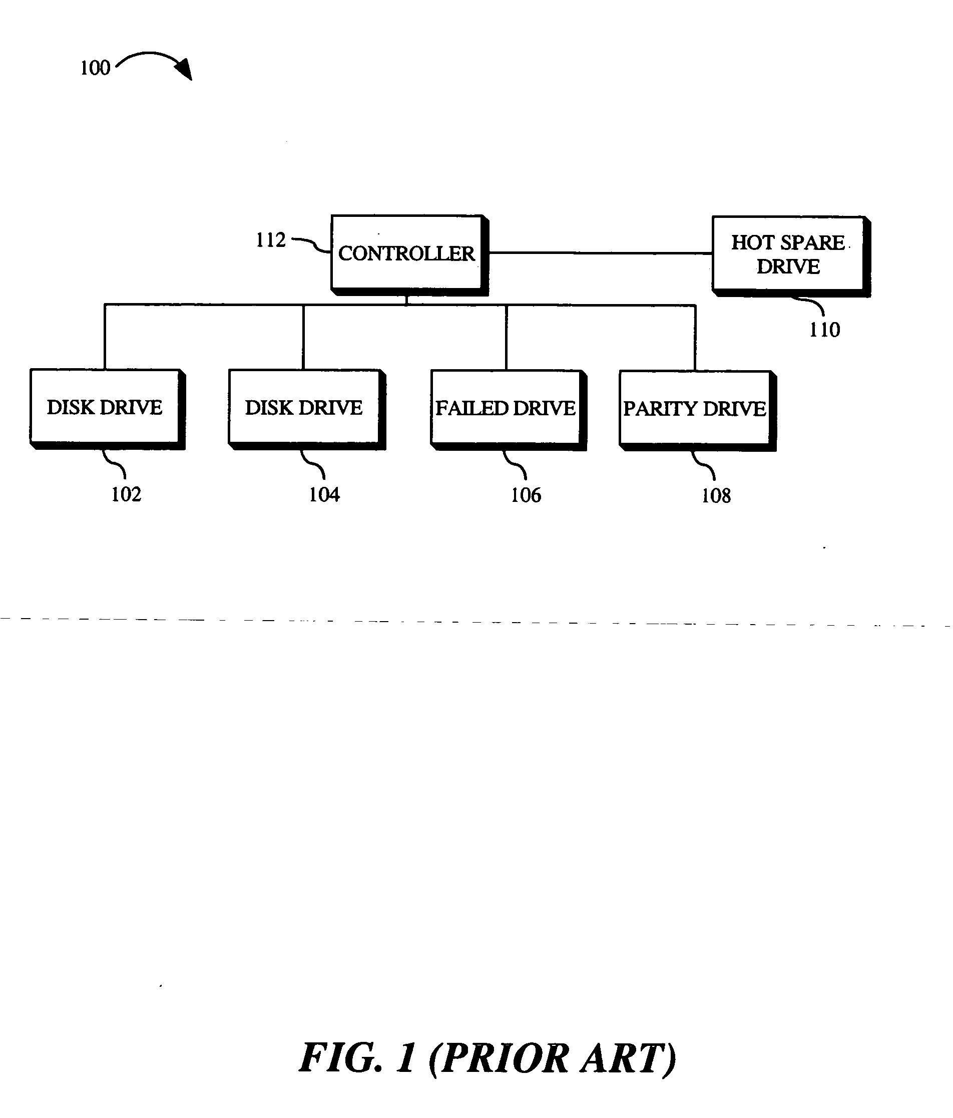
[0014]FIG. 1 illustrates a typical RAID (Redundant Array of Independent Disks) configuration 100. Included in the configuration are a plurality of RAID disk drives (102, 104, 106 and 108). One of the RAID disk drives 108 is a dedicated parity drive (generally used in RAID 3 configurations). The dedicated parity drive 108 contains parity information which allows for data recovery / reconstruction if one of the RAID disk drives (102, 104 or 106) fails. Also included in the above-referenced configuration is a hot spare disk drive 110. A hot spare disk drive 110 is a disk drive that is called into use, typically by a RAID controller 112, upon the failure of one of the RAID disk drives. In the RAID configuration illustrated in FIG. 1, one of the RAID disk drives 106 has failed. Upon failure of the RAID disk drive 106, the hot s...


PUM


Abstract

The present invention is a system for reducing rebuild time in a RAID (Redundant Array of Independent Disks) configuration. The system includes a plurality of RAID disk drives, a plurality of hot spare disk drives, and a controller communicatively coupled to the plurality of RAID disk drives and the plurality of hot spare disk drives. The system functions so that rebuild data is striped by the controller across at least two hot spare disk drives included in the plurality of hot spare disk drives.

Description

FIELD OF THE INVENTION [0001] The present invention relates to the field of electronic data storage and particularly to a system and method for reduction of rebuild time in RAID (Redundant Array of Independent Disks) systems through implementation of striped hot spare drives. BACKGROUND OF THE INVENTION [0002] A number of RAID systems currently support the use of hot spare disk drives. A hot spare disk drive is a drive that is in standby mode and is designated for use if a disk drive in a RAID array fails. Upon failure of a disk drive in a RAID array, a RAID controller may automatically begin to “rebuild” the data of the failed disk drive via a rebuild process, which involves reconstructing the data of the failed disk drive using data from one or more of the remaining functional disk drives in the RAID array and writing the reconstructed data (i.e., the rebuild data) to the hot spare disk drive. Once the rebuild process is complete and the failed disk drive is replaced-by a replacem...

Claims


Application Information

Patent Timeline
IPC IPC(8): G11B20/20
CPCG11B20/20G06F11/1088
Inventor SCHMITZ, THOMAS A.
Owner LSI CORPORATION
Learn More