Dimming ballast control circuit

a ballast control and ballast technology, applied in the direction of instruments, light sources, electrical devices, etc., can solve the problems of unnecessarily complex ballast control integrated circuits, and achieve the effect of reducing pins and components

Inactive Publication Date: 2007-04-26
INFINEON TECH AMERICAS CORP
View PDF11 Cites 28 Cited by
  • Summary
  • Abstract
  • Description
  • Claims
  • Application Information

AI Technical Summary

Benefits of technology

[0005] It is an object of the present invention to provide a dimming ballast control circuit with a reduced pin and component count. The circuit includes a driver circuit for driving high and low side switches of a ballast power switching circuit, a control circuit for driving the driver circuit including an oscillator circuit for providing an oscillating signal to control the frequency of operation of the power switching circuit; the power switching circuit providing lamp powering pulsed signals; and a dimmi...

Problems solved by technology

Ballast control integrated circuits often are unnecessarily complex from the standpoint of th...

Method used


Image

  • Dimming ballast control circuit
  • Dimming ballast control circuit
  • Dimming ballast control circuit

Examples


Embodiment Construction

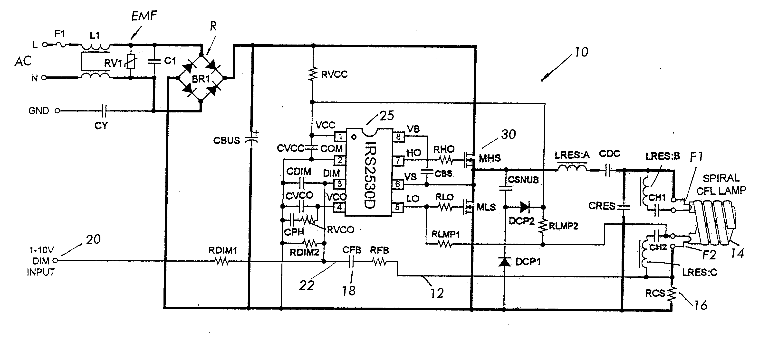
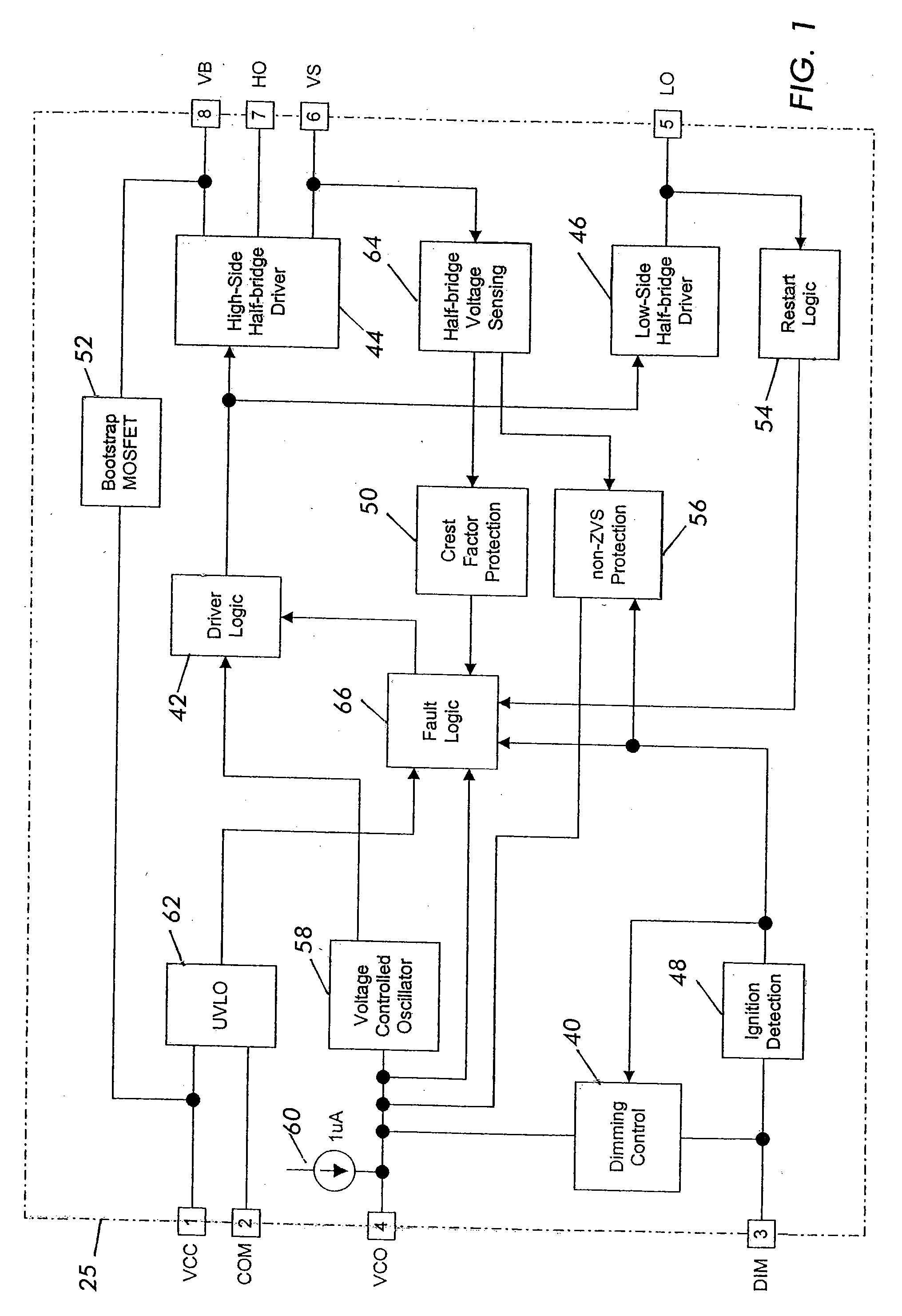
[0012]FIG. 1 illustrates an 8-pin dimming ballast control integrated circuit (IC) 25. FIG. 4 shows the IC 25 in a ballast circuit powering a lamp 14. The IC 25 realizes a simple, high-performance dimming ballast solution. In the embodiment shown, the ballast control is obtained by an integrated circuit having only 8 pins. VCC pin 1 supplies a logic and internal gate drive power voltage VCC for powering the IC. This voltage is also provided to an Undervoltage Lockout (UVLO) circuit 62 and the bootstrap switch 52. UVLO circuit 62 provides under voltage lock out protection to prevent operation of the output driver stage when Vcc is below a threshold level. Bootstrap circuit 52 provides the high side driver stage voltage for powering the high side driver at a voltage level VB above voltage VCC. COM pin 2 is the IC power and signal ground also provided to the UVLO circuit 62. Signals from the UVLO circuit 62 are provided to a Fault Logic circuit 66.

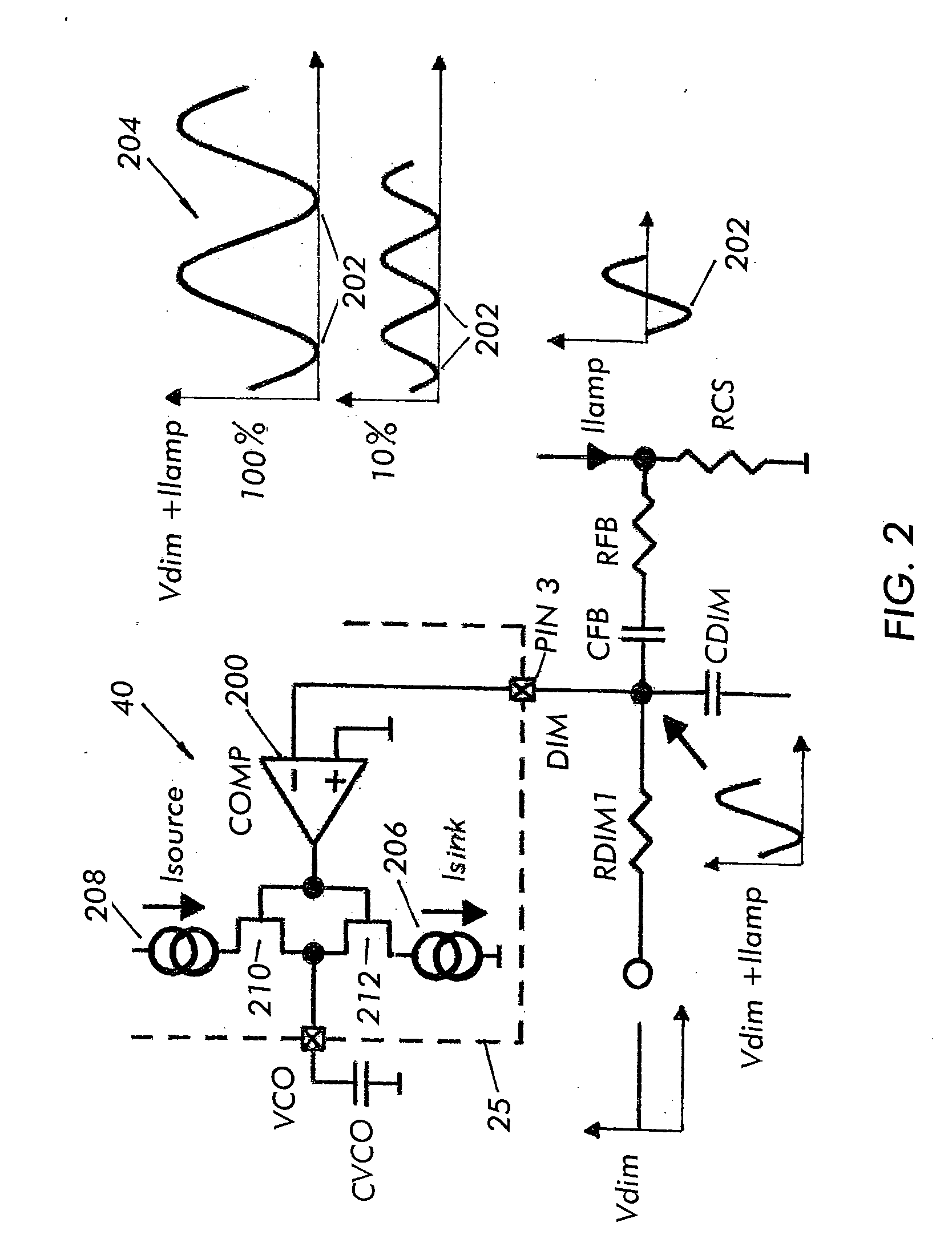
[0013] DIM pin 3 provides a dimming co...


PUM


Abstract

A dimming ballast control circuit for driving a ballast power switching circuit powering a gas discharge lamp. The circuit includes a driver circuit for driving high and low side switches of the ballast power switching circuit; a control circuit for driving the driver circuit including an oscillator circuit for providing an oscillating signal to control the frequency of operation of the ballast power switching circuit, the ballast power switching circuit outputting lamp powering pulsed signals; and a dimming control circuit having an input, the dimming control circuit receiving an AC lamp current feedback signal at the input, the dimming control circuit further receiving a DC input voltage reference at the input whereby the DC input voltage reference determines a desired dimming level of the lamp and the AC lamp current feedback signal maintains the lamp brightness at the desired dimming level.

Description

CROSS-REFERENCE TO RELATED APPLICATION [0001] This application is based on and claims the benefit of U.S. Provisional Application Ser. No. 60 / 729,586, filed on Oct. 24, 2005, entitled DIMMING BALLAST CONTROL INTEGRATED CIRCUIT, to which a claim of priority is hereby made and the disclosure of which is incorporated by reference.BACKGROUND OF THE INVENTION [0002] The present invention relates to dimming ballast controls, and more particularly to a dimming ballast control integrated circuit for controlling a ballast driving a gas discharge lamp, for example, a fluorescent lamp or a compact fluorescent lamp. [0003] Ballast control integrated circuits often are unnecessarily complex from the standpoint of the number of pins / connections necessary to implement a ballast circuit using the integrated circuit. Often, these circuits have over 8 pins and if a dimming function is included, a separate pin is required for both setting the dimming level and for feedback control to maintain the desi...

Claims


Application Information

Patent Timeline
IPC IPC(8): H05B41/36
CPCH05B41/2981H05B41/3925Y10S315/04H05B41/24H05B41/38
Inventor RIBARICH, THOMAS J.
Owner INFINEON TECH AMERICAS CORP
Why Eureka
Try Eureka