
Devices powered by conformable fuel cells

Inactive Publication Date: 2007-04-26
INTELLIGENT ENERGY LTD
View PDF15 Cites 57 Cited by
  • Summary
  • Abstract
  • Description
  • Claims
  • Application Information

AI Technical Summary

Benefits of technology

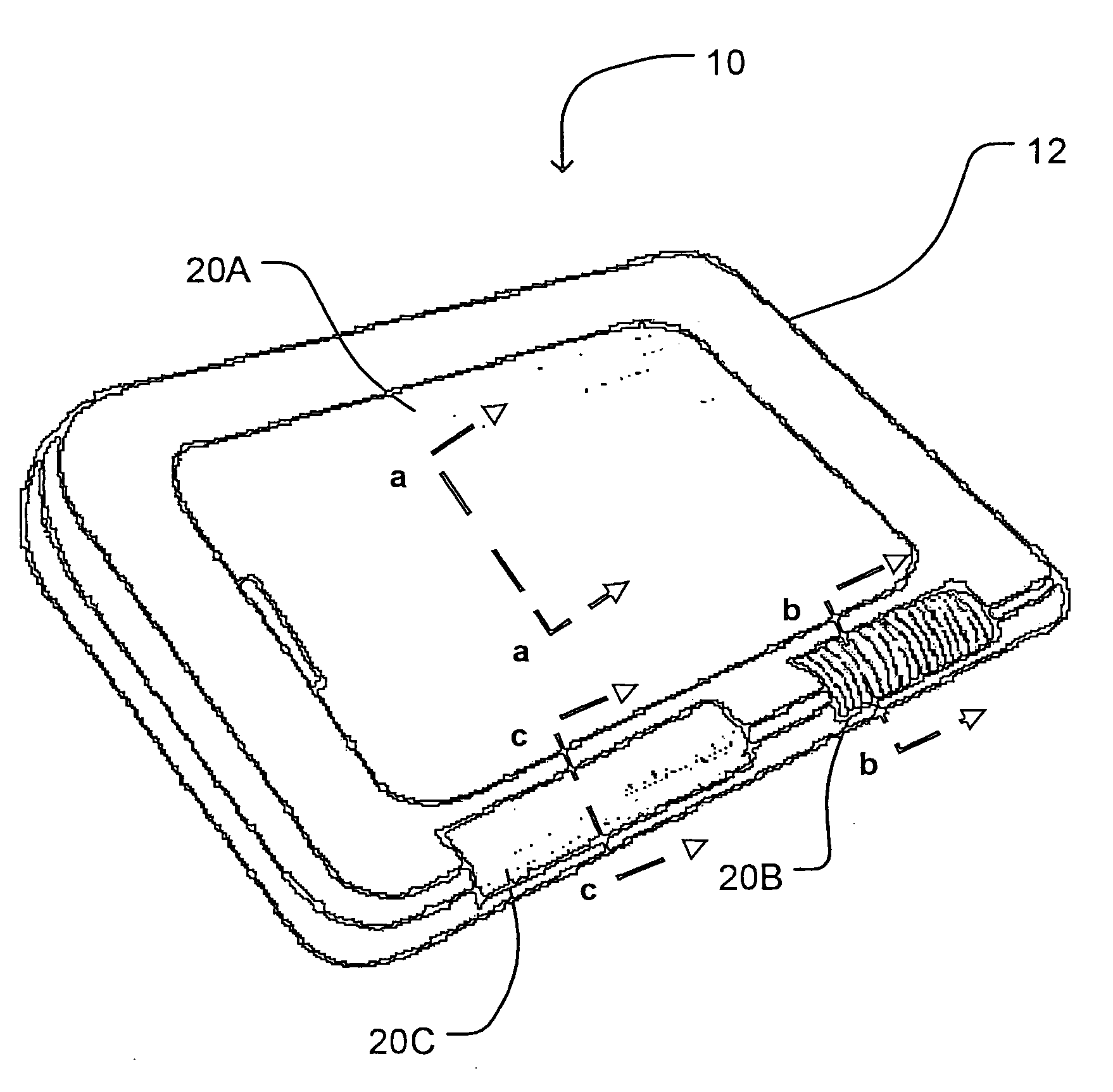
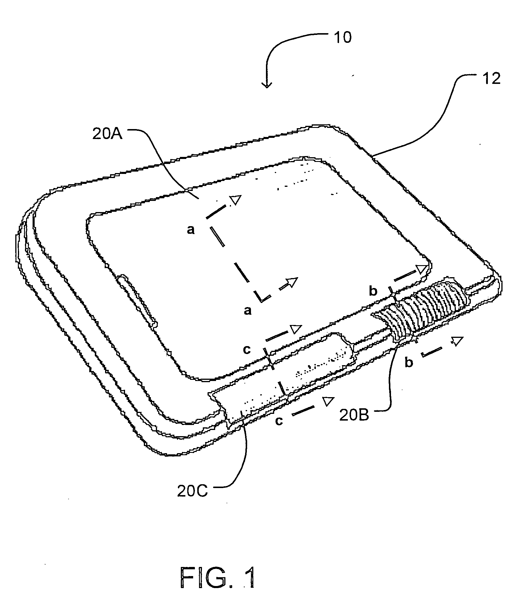
[0008] One aspect of the invention provides a fuel cell system that can be conformed to structural aspects of a device which it powers. This aspect of the invention provides an array of fuel cells in a thin 2-dimensional layer,

Problems solved by technology

For large stationary devices, the volume requirements of conventional fuel cell stacks

Method used


Image

  • Devices powered by conformable fuel cells
  • Devices powered by conformable fuel cells
  • Devices powered by conformable fuel cells

Examples


Example

[0020] Throughout the following description, specific details are set forth in order to provide a more thorough understanding of the invention. However, the invention may be practiced without these particulars. In other instances, well known elements have not been shown or described in detail to avoid unnecessarily obscuring the invention. Accordingly, the specification and drawings are to be regarded in an illustrative, rather than a restrictive, sense.

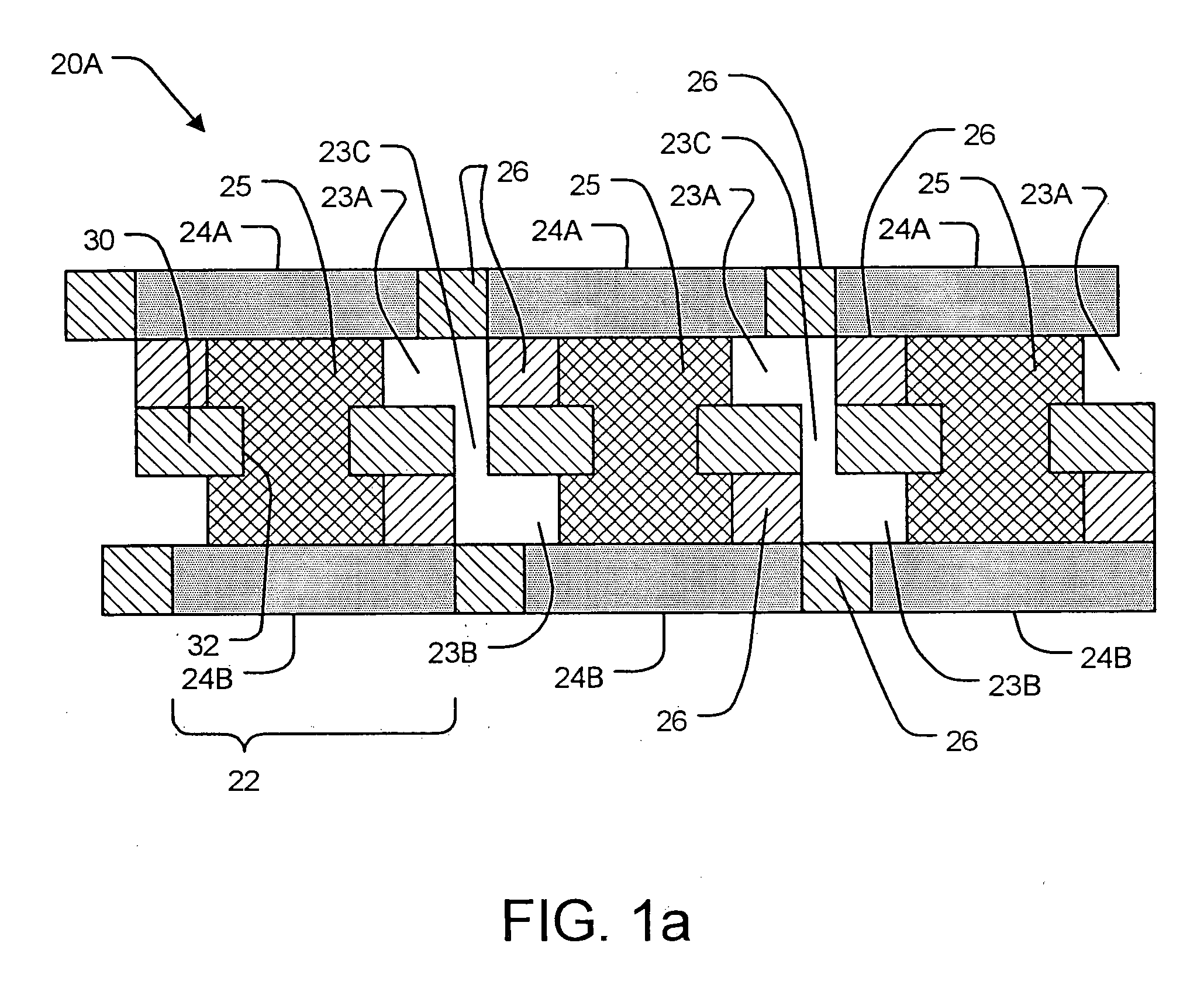
[0021] This invention exploits the fact that it is possible to make arrays of fuel cells which are thin in one dimension and spread to cover a surface in another dimension, the surface need not be planar. Such fuel cell arrays are termed “2D fuel cell arrays” herein. There are various constructions which may be used to make 2D fuel cell arrays.

[0022] A 2D fuel cell array may be made up of individual fuel cells that are arranged two-dimensionally in any of various suitable ways on an area covered by the 2D array. For example, cathod...


PUM


Abstract

Thin layers of fuel cells are provided on the housings of portable electrically-powered devices. The fuel cells provide electrical power for the devices. The fuel cell layers can follow contours of the device housings. some embodiments provide fuel plenums between a surface of the housing and a fuel cell layer. The fuel plenum may carry a fuel such as hydrogen gas to fuel cells of the fuel cell layer.

Description

CROSS-REFERENCE TO RELATED APPLICATION [0001] This application claims the benefit under 35 U.S.C. §119 of U.S. patent application No. 60 / 589,583 filed on 21 Jul. 2004 and entitled CONFORMABLE FUEL CELLS, which is hereby incorporated by reference herein.TECHNICAL FIELD [0002] The invention relates to fuel cells, and particularly to devices which include fuel cells to provide electrical power. BACKGROUND [0003] Fuel cells can convert suitable hydrogen or hydrocarbon fuels directly into electrical power. As such, fuel cells have promise as a source of clean energy. Fuel cells have been proposed as power sources for devices as diverse as automobiles, personal computers and flashlights. Fuel cells are typically arranged in stacks. A stack configuration provides a maximized volumetric power density. The fuel cells in a typical stack each have a membrane electrode assembly (MEA). Flow field plates are located on either side of the MEA. The flow field plates are typically rigid. The flow fi...

Claims


Application Information

Patent Timeline
IPC IPC(8): H02J7/00
CPCB64D41/00B64D2041/005H01M8/006H01M8/0256H01M8/1002H01M8/2475H01M2250/20H01M2250/30Y02B90/18Y02E60/521Y02T90/32Y02T90/36H01M8/1007Y02B90/10Y02T90/40Y02E60/50
Inventor MCLEAN, GERARD FRANCIS
Owner INTELLIGENT ENERGY LTD
Learn More