
Method and a sensor device for measuring the distance between a stator and an opposing rotor

a sensor device and stator technology, applied in the field of measuring distance, can solve the problems of only carrying out calibration and monitoring of the sensor, the size of the grinding gap between the stator and the rotor changes during operation, and the effect of zero setting

Active Publication Date: 2007-04-26
DAPROKS AB
View PDF6 Cites 5 Cited by
  • Summary
  • Abstract
  • Description
  • Claims
  • Application Information

AI Technical Summary

Benefits of technology

[0005] The object of the invention is to make it possible to determine with increased precision the distance between stator and rotor in machines of the stated type. Another object is to achieve a simple solution. DISCLOSURE OF INVENTION
[0007] By utilizing a stop located close to the measuring end of the sensor body, it is possible to obtain a movement of the sensor body that is well-defined as far as distance is concerned at the end where measurement takes place, and by this means a more precise calibration can be carried out than what was possible previously.

Problems solved by technology

In refiners designed for the manufacture of paper pulp, the size of the grinding gap between a stator and a rotor changes during operation as a result of wear on the grinding segments on the stator and rotor that face each other.
One of the disadvantages of such a method is that it can only be used on machines where the rotor can be operated with precision, as otherwise the wear caused by the zero-setting can be considerable and, in addition, the calibration and monitoring of the sensor can only be carried out during idle running.
This results in a relatively large distance between the measurement position and the end surface of the sensor, with consequent difficulties in ensuring the required precision in the measurements, as during operation the sensor is often subjected to a change in length due to temperature variations.

Method used


Image

  • Method and a sensor device for measuring the distance between a stator and an opposing rotor
  • Method and a sensor device for measuring the distance between a stator and an opposing rotor

Examples


Embodiment Construction

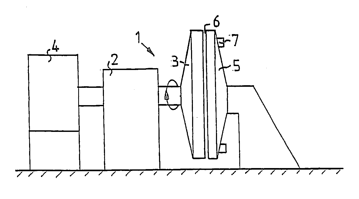
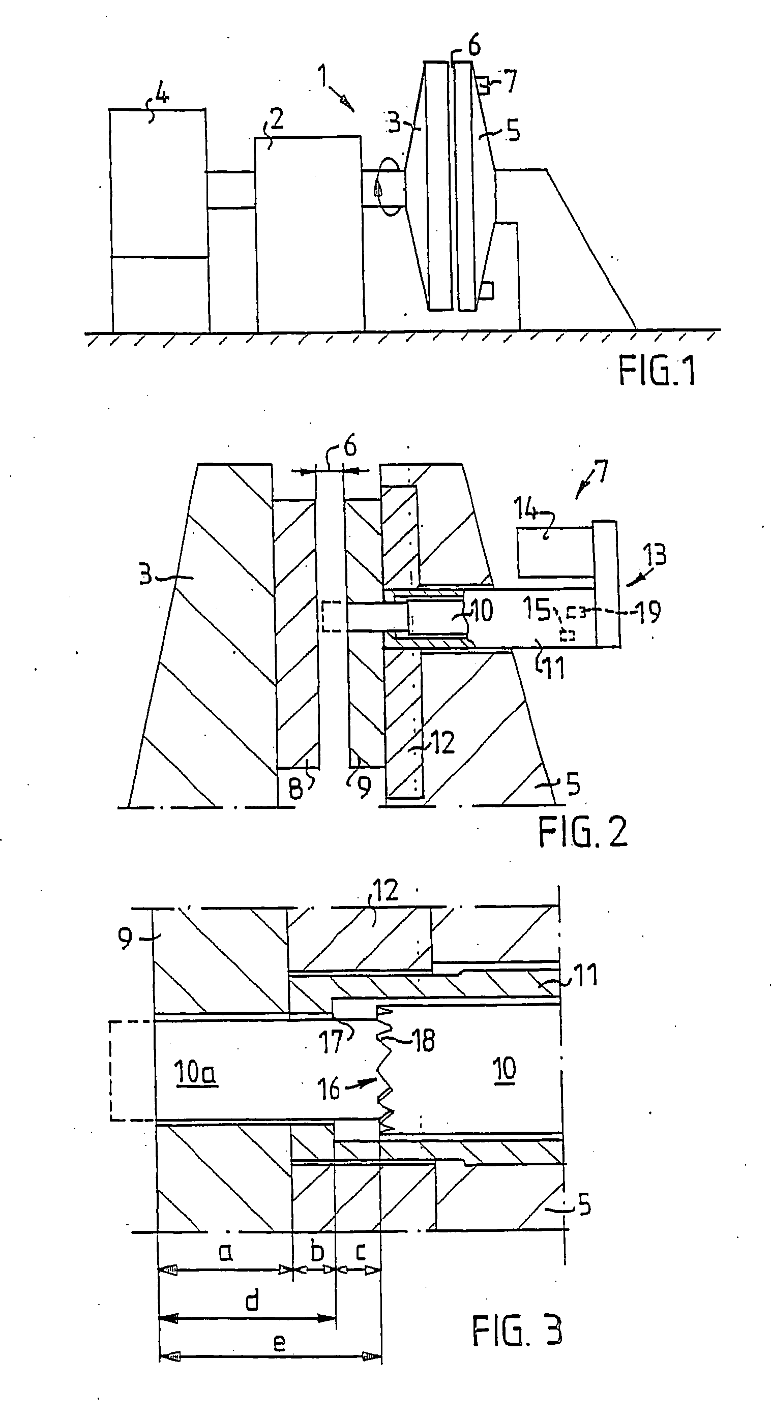
[0014]FIG. 1 shows schematically a machine 1 of the refiner type designed for paper pulp manufacture, in which the invention is utilized. This machine is provided with a rotor 3, mounted in a framework 2 in such a way that it can rotate, which rotor is driven by a motor 4 and can also be moved axially in a direction to and from a stator 5 in order to adjust the size of a grinding gap 6 between the rotor 3 and the stator 5. For monitoring the size of the grinding gap 6 at least one sensor device 7 is mounted in the stator 5, with a sensor that is of the magnetic type and operates suitably according to the reluctance principle. This type of sensor is well known to experts within the field. There can suitably be two or more sensor devices 7 distributed around the stator 5.

[0015] As shown in greater detail in FIG. 2, both the rotor 3 and the stator 5 are provided with a suitable number of grinding segments 8, 9 that have a surface suitable for grinding paper pulp and that are mounted i...


PUM

PropertyMeasurementUnit
sizeaaaaaaaaaa
diameteraaaaaaaaaa
lengthaaaaaaaaaa

Abstract

A sensor device for measuring distance between a stator and a rotor in a machine is of the magnetic type and is intended to be mounted in the stator in order to interact with an opposing surface on the rotor. A sensor body (10) can be moved axially in a housing (11) mounted in the stator by means of an operating mechanism (13) and has a stop (16) at a predetermined distance (e) from its end surface designed to interact with a corresponding stop (17) inside the housing. This distance (e) exceeds the distance (d) between the stop (17) in the hosing and the end of the sensor body (10) by a predetermined distance (c) when the sensor body is in its normal measuring position. These stops (16, 17) make possible a particularly accurate calibration of the sensor device.

Description

TECHNICAL FIELD [0001] The present invention relates to a method for measuring distance according to the preamble to Claim 1, and to a sensor device for measuring distance according to the preamble to Claim 3. BACKGROUND ART [0002] In refiners designed for the manufacture of paper pulp, the size of the grinding gap between a stator and a rotor changes during operation as a result of wear on the grinding segments on the stator and rotor that face each other. For reasons of quality, it is desirable to have good control over the size of the grinding gap and to be able to change the size of the grinding gap in order, for example, to be able to compensate for wear. Refiners of this type have normally long operating periods, often several months, for which reason monitoring of the size of the grinding gap should be able to be carried out during operation. [0003] In order to measure the size of the grinding gap, it is customary to use sensors of the magnetic type that are positioned statio...

Claims


Application Information

Patent Timeline
Patent Type & Authority Applications(United States)
IPC IPC(8): G01B7/30B02C7/14D21D1/00D21D1/30G01B7/14H02K11/00
CPCB02C7/14D21D1/002D21D1/30G01B7/14H02K11/001H02K11/20
Inventor AKERBLOM, BENGT
Owner DAPROKS AB
Learn More