Method and device for moving a tomography apparatus gantry

a tomography and gantry technology, applied in the direction of lifting devices, mobile jacks, electrical devices, etc., can solve the problems of metric ton and inconvenient use of elevators, and achieve the effect of simplifying the introduction of gantry

Active Publication Date: 2007-04-26
SIEMENS AG
View PDF0 Cites 24 Cited by
  • Summary
  • Abstract
  • Description
  • Claims
  • Application Information

AI Technical Summary

Benefits of technology

[0005] An object of the present invention is to provide a device of the aforementioned type as well as a method using suc

Problems solved by technology

Often there are halls leading to the installation site, or stairways or doors leading into the installation room of the tomography apparatus, that are too narrow or too small to allow the gantry to be brought to its operation location in a conventional manner.
When the operation location of the gantry is located

Method used


Image

  • Method and device for moving a tomography apparatus gantry
  • Method and device for moving a tomography apparatus gantry
  • Method and device for moving a tomography apparatus gantry

Examples


Embodiment Construction

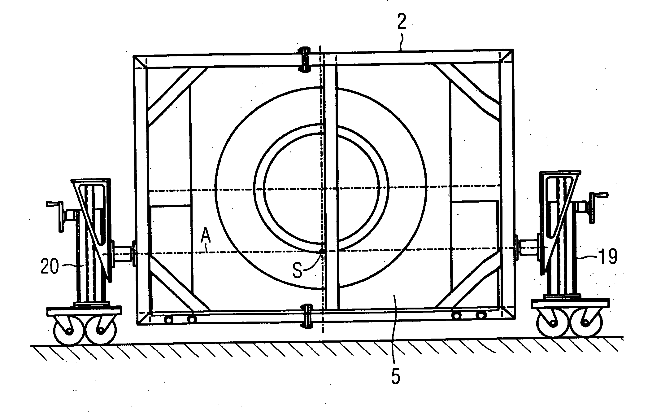
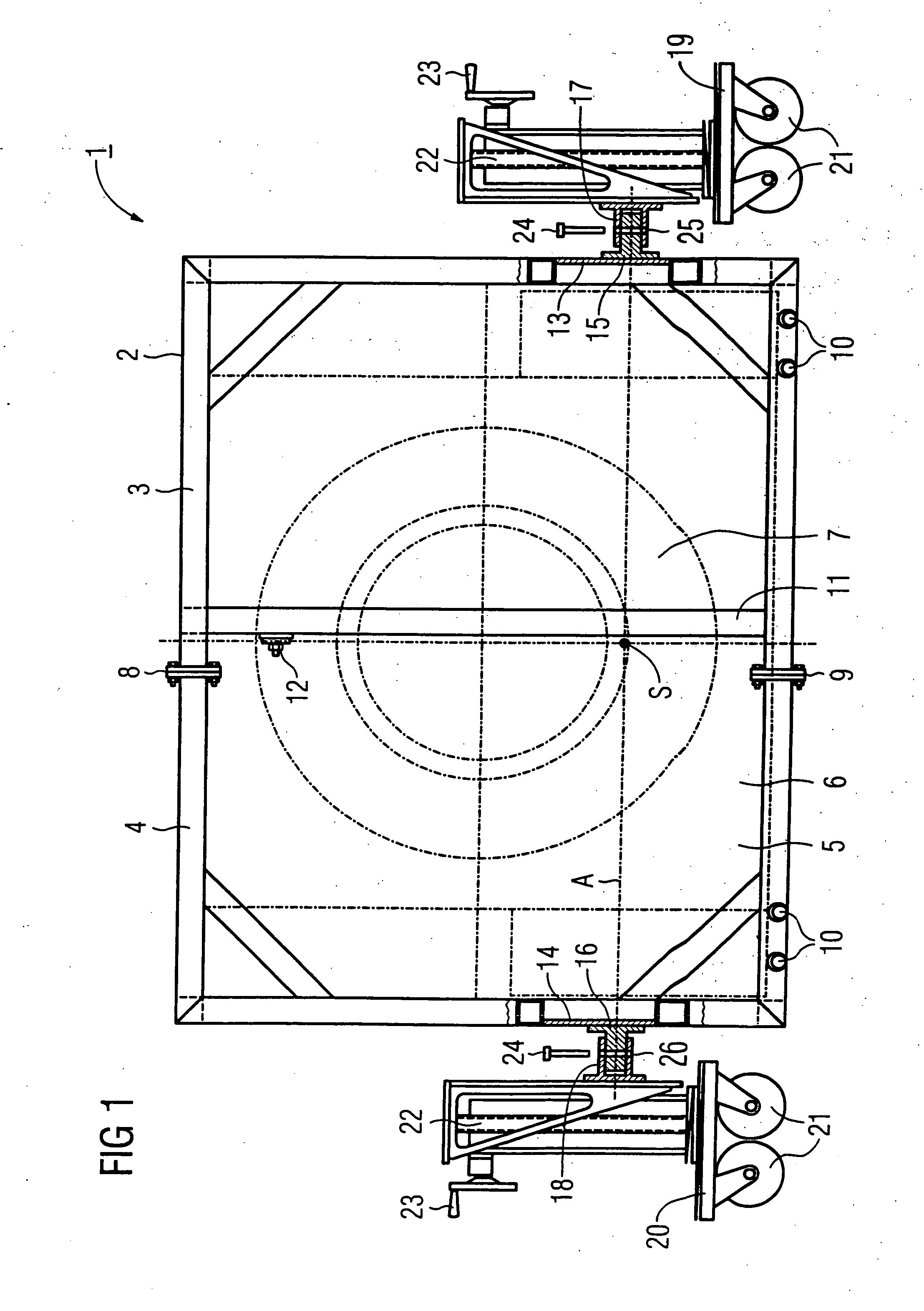
[0019]FIG. 1 illustrates a device 1 for moving a gantry of a tomography apparatus for horizontal introduction of the gantry into a building or into a room. In the exemplary embodiment the device 1 has a cuboid frame 2 that is composed of two partial frames 3 and 4. The frame 2 effectively forms a type of cage for a gantry 5 (indicated in FIG. 1 with dashed lines) which, in the case of the exemplary embodiment, is a gantry of an x-ray computed tomography apparatus, the patient positioning device of which is not shown. The gantry 5 has a part 6 that is stationary during operation of the x-ray computed tomography apparatus and a rotatable part 7. The rotatable part has (in a known manner not shown in the figures) a rotor as well as an x-ray source and an x-ray detector that are arranged opposite one another on the rotor. The measurement system of the gantry 5, which measurement system includes the x-ray source and the x-ray detector, is highly sensitive and therefore must be carefully ...


PUM


Abstract

In a method and device for a moving gantry of a tomography apparatus for horizontal introduction of the gantry into a building or a room, a frame accommodates the gantry and two lifting devices which can respectively be connected with the frame via supports such that a pivot axis extending through the supports around which pivot axis the frame with the gantry can be pivoted, proceeds substantially through the center of gravity of the frame provided with the gantry.

Description

BACKGROUND OF THE INVENTION [0001] 1. Field of the Invention [0002] The present invention concerns a device for moving a gantry of a tomography apparatus which serves to bring the gantry into a building or into a room in which the tomography apparatus should be operated. The invention also concerns a method for moving a gantry for that purpose. [0003] 2. Description of the Prior Art [0004] Tomography apparatuses, which include x-ray computed tomography apparatuses, PET apparatuses, SPECT apparatuses and combination apparatuses of such modalities, have a gantry as well as a patient positioning device that can be connected with the gantry. The gantry, which can be separated from the patient positioning device (such as for the transport of the tomography apparatus from its manufacturing location to its installation or operation location in a clinic or a medical practice), frequently exhibits dimensions such that the gantry cannot be brought into the building or the room (which represen...

Claims


Application Information

Patent Timeline
IPC IPC(8): H05G1/02
CPCB66F5/025B66F9/06
Inventor ALBERT, LAURENTIUS
Owner SIEMENS AG
Why Eureka
Try Eureka