WDM type passive optical network

a passive optical network and optical network technology, applied in the field of passive optical network, can solve the problems of increasing the cost of the onus, not easy to add a new onus, and increasing the management cost of the type of pon system

Inactive Publication Date: 2007-04-26
HITACHI LTD
View PDF6 Cites 161 Cited by
  • Summary
  • Abstract
  • Description
  • Claims
  • Application Information

AI Technical Summary

Benefits of technology

[0025] An object of the present invention is to provide a WDM type PON system that has made increasing ONUs easier.
[0027] Further object of the present invention is to provide a WDM type PON system that has made it possible to make effective use of communication resources in the optical fiber section and widen the communication bandwidth for each ONU by dynamically allocating to each ONU a dedicated wavelength different from the wavelengths allocated to other ONUs, for both upstream and downstream signals.
[0033] According to the present invention, when a new ONU is added to the PON, the engineer involved does not need to care for wavelengths to be used by the additional ONU, since each ONU is able to autonomously start data transmission and reception at individual transmitting and receiving wavelengths specified from the OLT.

Problems solved by technology

Consequently, this scheme increases the cost of the ONUs much greater than in the first scheme.
In order to accommodate a new subscriber terminal to the OLT, it is necessary for the second scheme to prepare an ONU that has upstream / downstream wavelengths other than the wavelengths for the existing ONUs and to connect the ONU to an appropriate port of the splitter / filter and, thus, is not easy to add a new ONU.
Further, this type of PON system involves increased management cost because it requires to record wavelengths currently used in preparation for increasing ONUs later.

Method used


Image

  • WDM type passive optical network
  • WDM type passive optical network
  • WDM type passive optical network

Examples


Embodiment Construction

[0046] Preferred embodiments of the present invention will be described hereinafter with reference to the drawings.

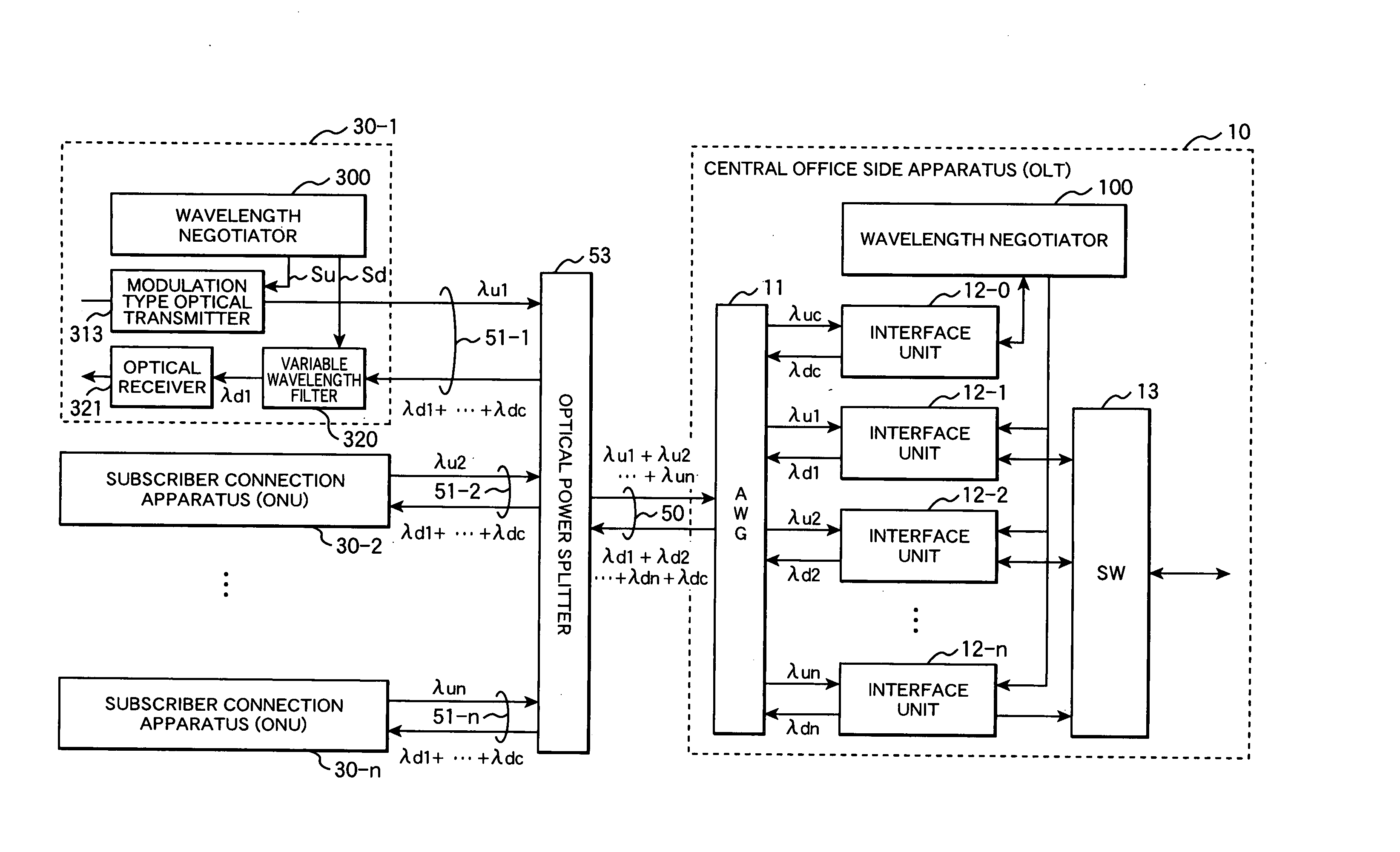
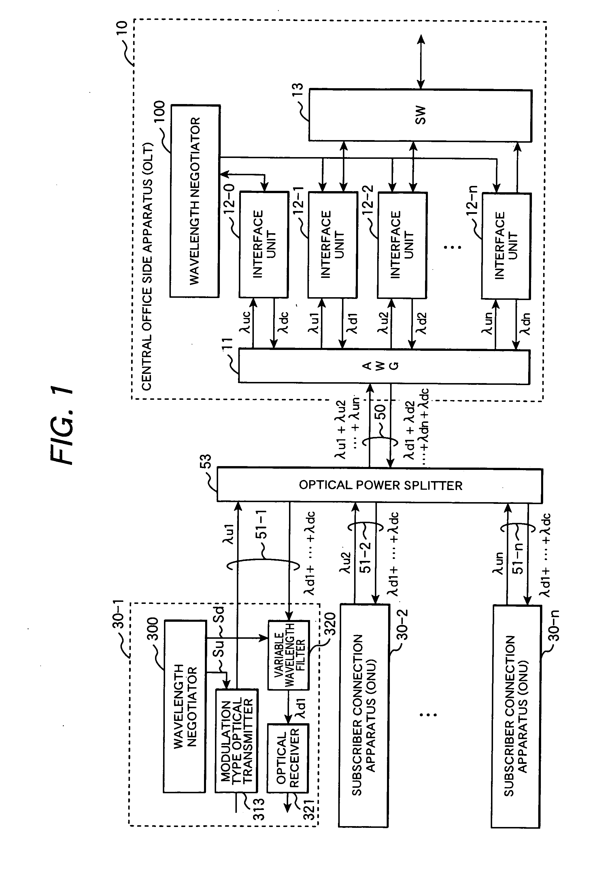
[0047]FIG. 1 is a structural diagram showing an embodiment of a WDM-PON system according to the present invention.

[0048] The PON system of the present invention comprises an central office side apparatus (OLT) 10, a plurality of subscriber connection apparatuses (ONUs) 30 (30-1 to 30-n), and a passive optical network in which an optical fiber 50 and a plurality of branch optical fibers 51 (51-1 to 51-n) are linked via an optical power splitter 53.

[0049] Each ONU 30-j (j=1 to n) is equipped with a modulation type optical transmitter 313 whose wavelength is variable and transmits an upstream optical signal to a branch optical fiber 51-j at a specific wavelength λuj (j=1 to n) allocated from the OLT. The upstream optical signal transmitted form each ONU is multiplexed together with upstream optical signals transmitted from other ONUs by the optical power splitter 53 and...


PUM


Abstract

In a WDM type PON system, each ONU comprises an optical transmitter capable to transmit optical signals with variable wavelengths, an optical signal receiving filter variable its receiving wavelength, and a control unit. An OLT selects in response to a wavelength allocation request from each ONU, a transmitting wavelength and a receiving wavelength out of currently free wavelengths and allocates these wavelengths to the requester ONT. The control unit of the ONU switches the transmitting wavelength of the optical transmitter and the receiving wavelength of the optical signal receiving filter to the wavelengths specified in a response message from the OLT and starts data communication.

Description

CLAIM OF PRIORITY [0001] The present application claims priority from Japanese patent application serial No. 2005-222483, filed on Aug. 8, 2005, the content of which is hereby incorporated by reference into this application. BACKGROUND OF THE INVENTION [0002] (1) Field of the Invention [0003] The present invention relates to a Passive Optical Network (PON) in which a plurality of subscriber connection apparatuses share a part of an optical transmission line and, more particularly, to a WDM type PON system utilizing an Optical Wavelength Division Multiplexing (WDM) technique for multiplexing a plurality of optical signals with different wavelengths in the PON. [0004] (2) Description of Related Art [0005] A Passive Optical Network (PON) system is known as one of access network systems for point to multi-points (one to N) connection using optical signals. The PON system comprises a central office side apparatus OLT (Optical Line Terminal) placed at a facility center operated by a netwo...

Claims


Application Information

Patent Timeline
Patent Type & Authority Applications(United States)
IPC IPC(8): H04J14/00H04B10/27H04B10/272H04B10/524H04B10/572H04J14/02H04L12/44
CPCH04J14/0226H04J14/0282H04J14/0232H04J14/0238H04J14/0246H04J14/025H04J14/0252H04J14/0258H04J14/0267
Inventor NOZUE, DAIKIMIYATA, HIROAKISUEYOSHI, NORIYUKI
Owner HITACHI LTD
Why Eureka
Try Eureka