Image forming apparatus and control method of that apparatus

a technology of image forming apparatus and control method, which is applied in the direction of electrographic process apparatus, instruments, optics, etc., can solve the problems of insufficient study on the control technique enabling the apparatus, the position operation is disabled, and the cover is closed, so as to reduce the wasteful power consumption without impairing the user's convenience, reduce the wasteful power consumption, and reduce the effect of power consumption

Inactive Publication Date: 2007-04-26
SEIKO EPSON CORP
View PDF4 Cites 18 Cited by
  • Summary
  • Abstract
  • Description
  • Claims
  • Application Information

AI Technical Summary

Benefits of technology

[0015] According to the invention, the image forming apparatus including the process unit capable of being removably mounted in the apparatus body and the control method thereof are adapted to reduce the wasteful power consumption without impairing the user convenience in performing the operation of mounting / dismounting the process unit. According to the first aspect, the first standby mode is executed to enable the operation of the switching unit for shifting the apparatus to the state to permit the mounting / dismounting of the process unit, so that the mounting / dismounting of the process unit may be carried out while some parts of the apparatus, except for the switching unit, are deactivated. After the lapse of the predetermined length of time from the start of the first standby mode, the second standby mode is executed to deactivate the switching unit as well. Therefore, if the apparatus is left standstill in the course of performing the mounting / dismounting operation, the apparatus is shifted to the state to consume even less power after the lapse of the predetermined length of time. Thus is reduced the wasteful power consumption. In this manner, the invention ensures that a good efficiency of the operation of mounting / dismounting the process unit by the user is maintained while the wasteful power consumption is reduced even when the apparatus is left standstill in the course of the operation.
[0016] According to the second aspect, the power consumption during standby may be reduced by executing the power save mode in which the apparatus consumes less power. Furthermore, the apparatus is arranged such that despite the execution of the power save mode, the apparatus recovers from the power save mode when the cover member serving to restrict the mounting / dismounting operation by the user is opened. In the image forming apparatus according to the invention, the mounting / dismounting of the process unit is not permitted in the sate where the cover member is closed. The mounting / dismounting of the process unit is permitted only in the state where the cover member is opened. That is, the user takes the steps of first opening the cover member and then performing the mounting / dismounting of the process unit. Therefore, if the apparatus cancels the execution of the power save mode at the time when the cover member is opened, and is placed in the state to permit the operation of the switching unit, the apparatus is able to deal with the subsequent mounting / dismounting operation properly and quickly. Thus, the invention may constitute the image forming apparatus featuring the lower power consumption during standby and the good user convenience in performing the mounting / dismounting operation.
[0017] According to the third aspect in the case where the cover member is closed with the mounting / dismounting of the process unit yet to be done, the longer start waiting time than where the mounting / dismounting operation is followed by the closure of the cover member is provided before the mounting / dismounting inhibition process is started. If the user opens again the cover member during the start waiting time, the apparatus is maintained in the state to permit the mounting / dismounting of the process unit and hence, the user is allowed to proceed with the mounting / dismounting operation. Thus, the invention can improve the user convenience in performing the operation of mounting / dismounting the process unit.
[0018] According to the fourth aspect, the mounting / dismounting permission state corresponding to the image forming mode, and the mounting / dismounting permission state consuming less power and corresponding to the power save mode are discretely provided. Such a constitution permits the operation statuses of the parts of the apparatus in the mounting / dismounting permission state to be discretely set according to each operation mode. Therefore, the power consumed for performing the mounting / dismounting of the unit during the execution of the power save mode may be reduced, so that the power consumption may be even further reduced as compared with the apparatus wherein the power save mode is cancelled when the mounting / dismounting of the unit is to be performed. Whether in the image forming mode or in the power save mode, the apparatus permits the mounting / dismounting of the unit so that the mounting / dismounting operation may be performed efficiently. Thus, the image forming apparatus and the control method thereof according to the invention permit the user to perform the operation of mounting / dismounting the process unit efficiently and besides, reduce the wasteful power consumption.

Problems solved by technology

However, there may be a case where the user wants to replace the unit while the apparatus is on standby.
That is, this positioning operation is disabled if the power supply circuit is deactivated.
A sufficient study has not been made on a control technique enabling the apparatus to achieve both of these goals.
In cases, however, the user may make a mistake in the operation so that the cover is closed with the process unit such as the developer improperly dismounted / mounted.
This leads to vexations that the user must start the operation from the beginning again and besides, must wait till the apparatus is placed again in the state to permit the mounting / dismounting of the unit.

Method used


Image

  • Image forming apparatus and control method of that apparatus
  • Image forming apparatus and control method of that apparatus
  • Image forming apparatus and control method of that apparatus

Examples


first preferred embodiment

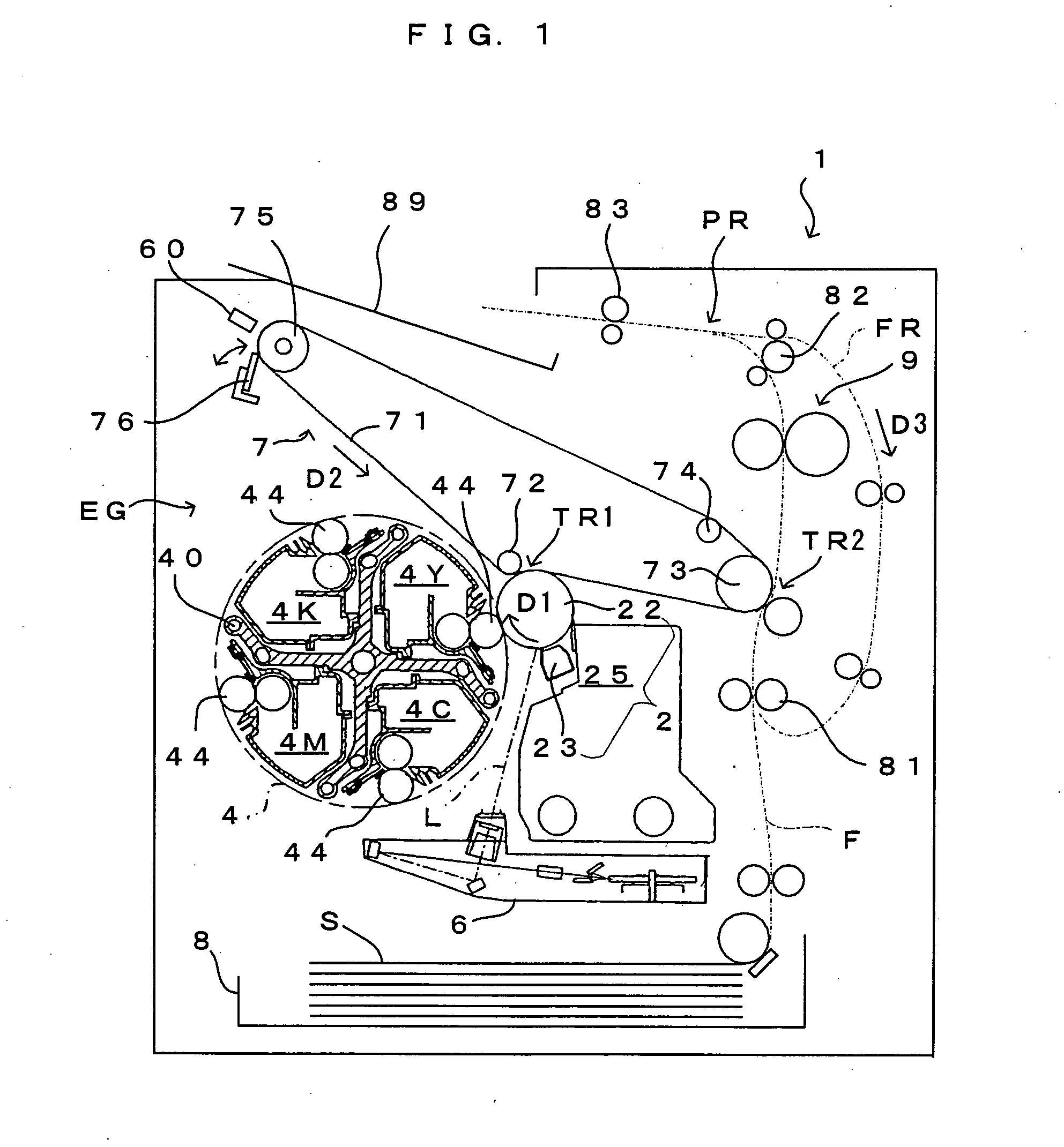
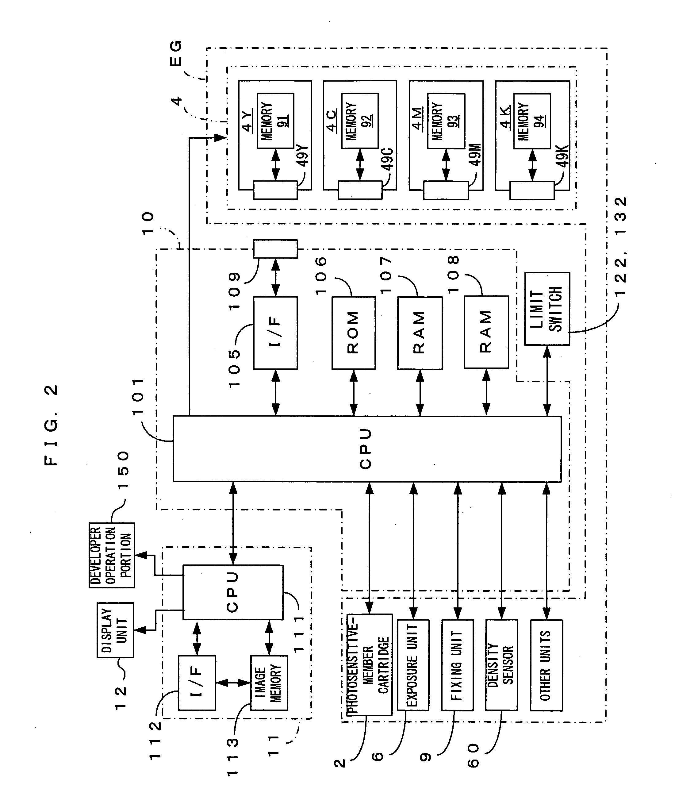
[0044]FIG. 1 is a drawing which shows a first preferred embodiment of an image forming apparatus according to the present invention. FIG. 2 is a block diagram which shows an electric structure of the apparatus of FIG. 1. This apparatus 1 is an image forming apparatus for forming a full color image by superimposing images of toners of four colors: yellow (Y), cyan (C), magenta (M) and black (K) and forming a monochromatic image only using the black (K) toner. In this image forming apparatus 1, when a print command signal including an image signal is given from an external apparatus such as a host computer to a main controller 11, an engine controller 10 controls individual parts of an engine section EG for executing a specified image forming operation in accordance with a command from the main controller 11, whereby an image corresponding to the image signal is formed on a sheet S.

[0045] In this engine section EG, a photosensitive member 22 is rotatably provided in a direction of ar...

second preferred embodiment

[0124]FIG. 14 is a drawing which shows an outside appearance of an image forming apparatus according to a second embodiment of the invention. A major difference between the apparatus of the second embodiment and the apparatus of the first embodiment consists in that the apparatus of the second embodiment is not provided with the inside cover for covering the developer opening. Accordingly, the apparatus of the second embodiment omits the arrangement for detecting the opening / closing of the inside cover. Otherwise, this apparatus is constructed substantially the same way as the apparatus of the first embodiment and hence, like parts are represented by the same reference characters, respectively, the description of which is dispensed with. Since an outside cover 320 and a developer opening 335 according to the second embodiment have different configurations from those of the corresponding components, the outside cover and the developer opening are represented by different reference ch...

third preferred embodiment

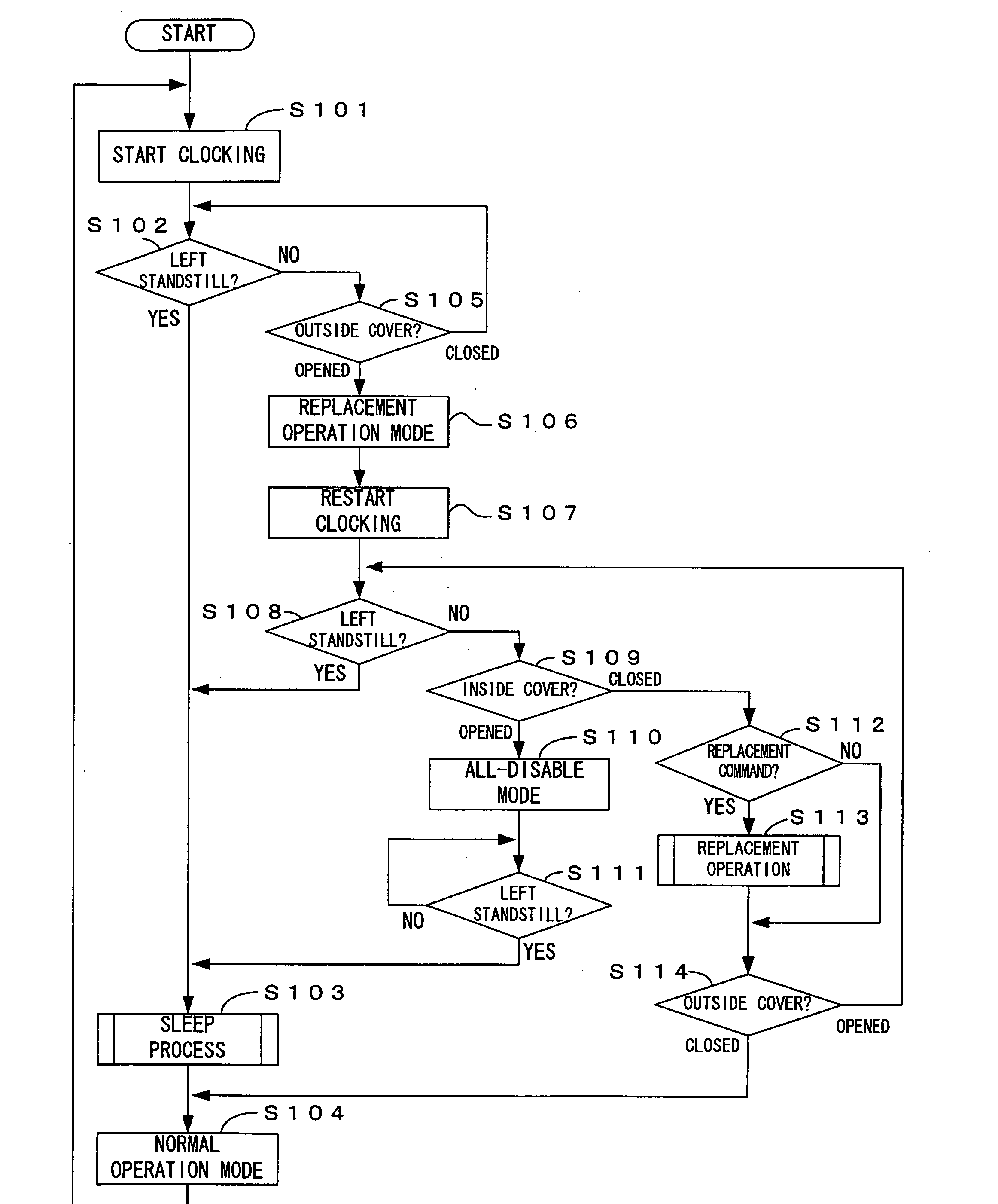
[0133] Next, description is made on an image forming apparatus according to a third embodiment of the invention. While the apparatus has the same mechanical construction as the above image forming apparatus of the second embodiment, the apparatus differs from that of the second embodiment in how the apparatus is shifted from one operation mode to another. A specific description is made on operation mode shifts which are characteristic of the third embodiment.

[0134] Similarly to the apparatuses of the foregoing first and second embodiments, the image forming apparatus of the embodiment positions the developing unit 4 at the home position when the apparatus is in the standby state where the image forming operation is not performed. Therefore, if the user opens the outside cover 320 to expose the developer opening 335, the user is not allowed to dismount the developer immediately.

[0135] In this image forming apparatus, the mounting / dismounting of the developer is not permitted until ...


PUM


Abstract

An image forming apparatus adapted for a smooth mounting / dismounting of a process unit and for the reduction of wasteful power consumption is provided. Unless a new image signal is applied after completion of an image forming operation, the apparatus starts a clocking operation by an internal timer (Step S101). If the apparatus is left standstill for a predetermined length of time (Step S102), a sleep process (Step S103) is executed to shift the apparatus to a power save mode to consume less power. When an outside cover is opened (Step S105), on the other hand, the apparatus is shifted to a replacement operation mode (Step S106) in which only the rotation of a development rotary is permitted. However, if the apparatus is left with the outside cover opened (Step S108), the sleep process is executed.

Description

TECHNICAL FIELD [0001] The present invention relates to an image forming apparatus including a process unit removably mountable in an apparatus body, and a control method thereof. BACKGROUND ART [0002] In image forming apparatuses such as printers, copiers and facsimile machines, the process unit is generally adapted to be removably mounted in the apparatus body for the purpose of replacing a consumable article. To manage use conditions of individual units for ensuring proper replacement of consumable articles, such apparatuses include one which is arranged to permit a user to perform a unit mounting / dismounting operation only when the apparatus is in a state to be able to confirm the mounting / dismounting of the unit. For instance, an image forming apparatus set forth in Patent Document 1 is arranged to permit the dismounting of a developing unit when a development rotary adapted to be removably mounted with the developing unit is rotatably positioned at a predetermined dismounting ...

Claims


Application Information

Patent Timeline
Patent Type & Authority Applications(United States)
IPC IPC(8): G03G15/00G03G15/01G03G21/00G03G21/14
CPCG03G15/5004G03G21/1839G03G2215/0177G03G15/0173G03G2221/183G03G15/0121G03G2221/169
Inventor NAKAZATO, HIROSHIIKUMA, KENTAGUCHI, KEIICHI
Owner SEIKO EPSON CORP
Why Eureka
Try Eureka