Scroll compressor

a compressor and scrolling technology, applied in the direction of machines/engines, rotary/oscillating piston pump components, liquid fuel engines, etc., can solve the problems of difficult assembly, etc., and achieve high efficiency, good sealing, and extremely accurate and expensive machining techniques.

Inactive Publication Date: 2007-04-26
EMERSON CLIMATE TECH INC
View PDF16 Cites 56 Cited by
  • Summary
  • Abstract
  • Description
  • Claims
  • Application Information

AI Technical Summary

Benefits of technology

[0003] Generally speaking, a scroll machine comprises two spiral scroll wraps of similar configuration, each mounted on a separate end plate to define a scroll member. The two scroll members are interfitted together with one of the scroll wraps being rotationally displaced 180° from the other. The machine operates by orbiting one scroll member (the “orbiting scroll”) with respect to the other scroll member (the “fixed scroll” or “non-orbiting scroll”) to make moving line contacts between the flanks of the respective wraps, defining moving isolated crescent-shaped pockets of fluid. The spirals are commonly formed as involutes of a circle, and ideally there is no relative rotation between the scroll members during operation; i.e., the motion is purely curvilinear translation (i.e., no rotation of any line in the body). The fluid pockets carry the fluid to be handled from a first zone in the scroll machine where a fluid inlet is provided, to a second zone in the machine where a fluid outlet is provided. The volume of a sealed pocket changes as it moves from the first zone to the second zone. At any one instant in time there will be at least one pair of sealed pockets; and where there are several pairs of sealed pockets at one time, each pair will have different volumes. In a compressor, the second zone is at a higher pressure than the first zone and is physically located centrally in the machine, the first zone being located at the outer periphery of the machine.
[0004] Two types of contacts define the fluid pockets formed between the scroll members, axially extending tangential line contacts between the spiral faces or flanks of the wraps caused by radial forces (“flank sealing”), and area contacts caused by axial

Problems solved by technology

One of the difficult areas of design in a scroll-type machine concerns the technique used to achieve tip sealing under all operating conditions, and also at all speeds in a variable speed machine.
Conventionally, this has been accomplished by (1) using extremely accurate and very expensive machini

Method used


Image

  • Scroll compressor
  • Scroll compressor
  • Scroll compressor

Examples


Embodiment Construction

[0036] The following description of the preferred embodiment(s) is merely exemplary in nature and is in no way intended to limit the invention, its application, or uses.

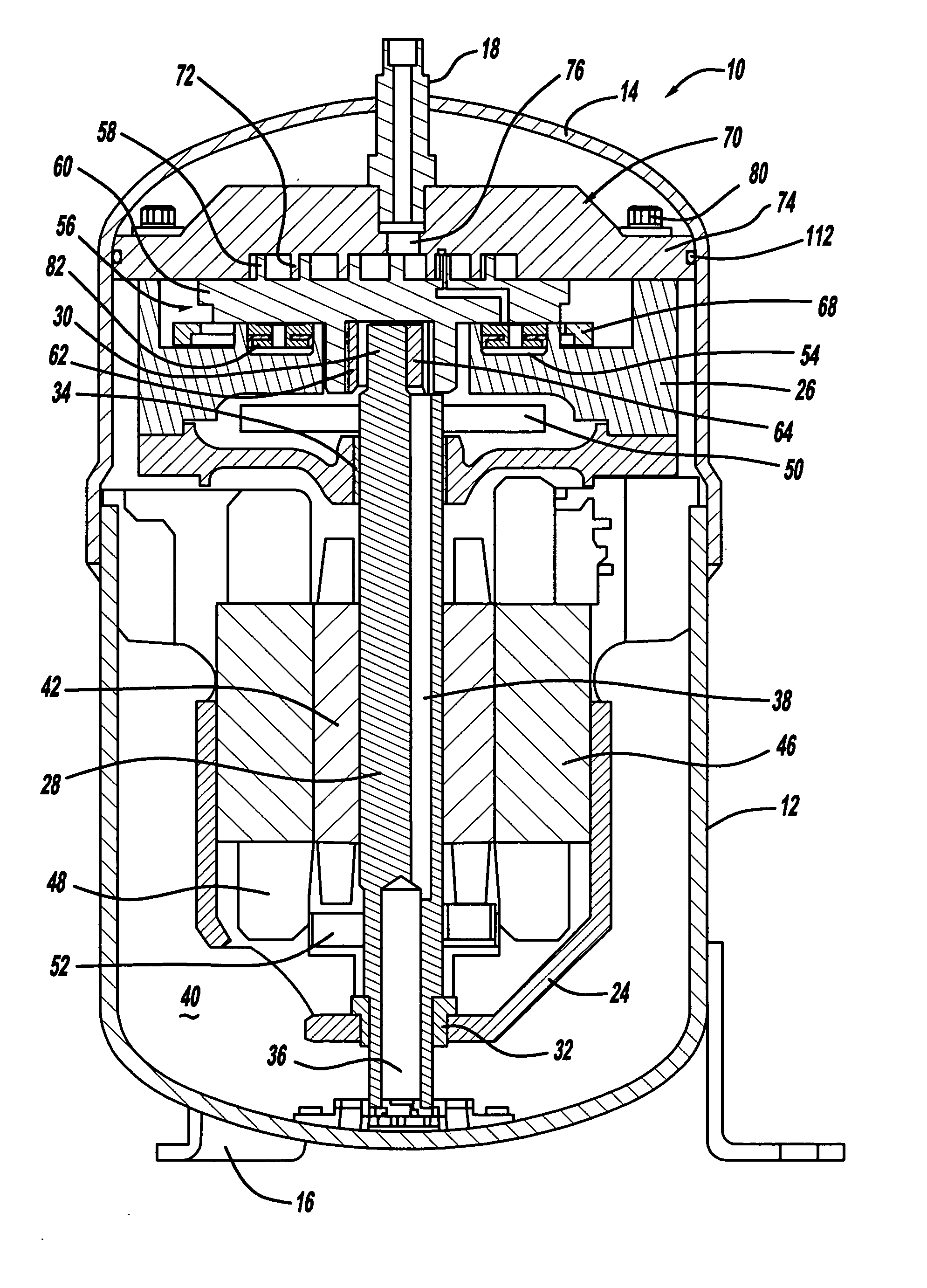
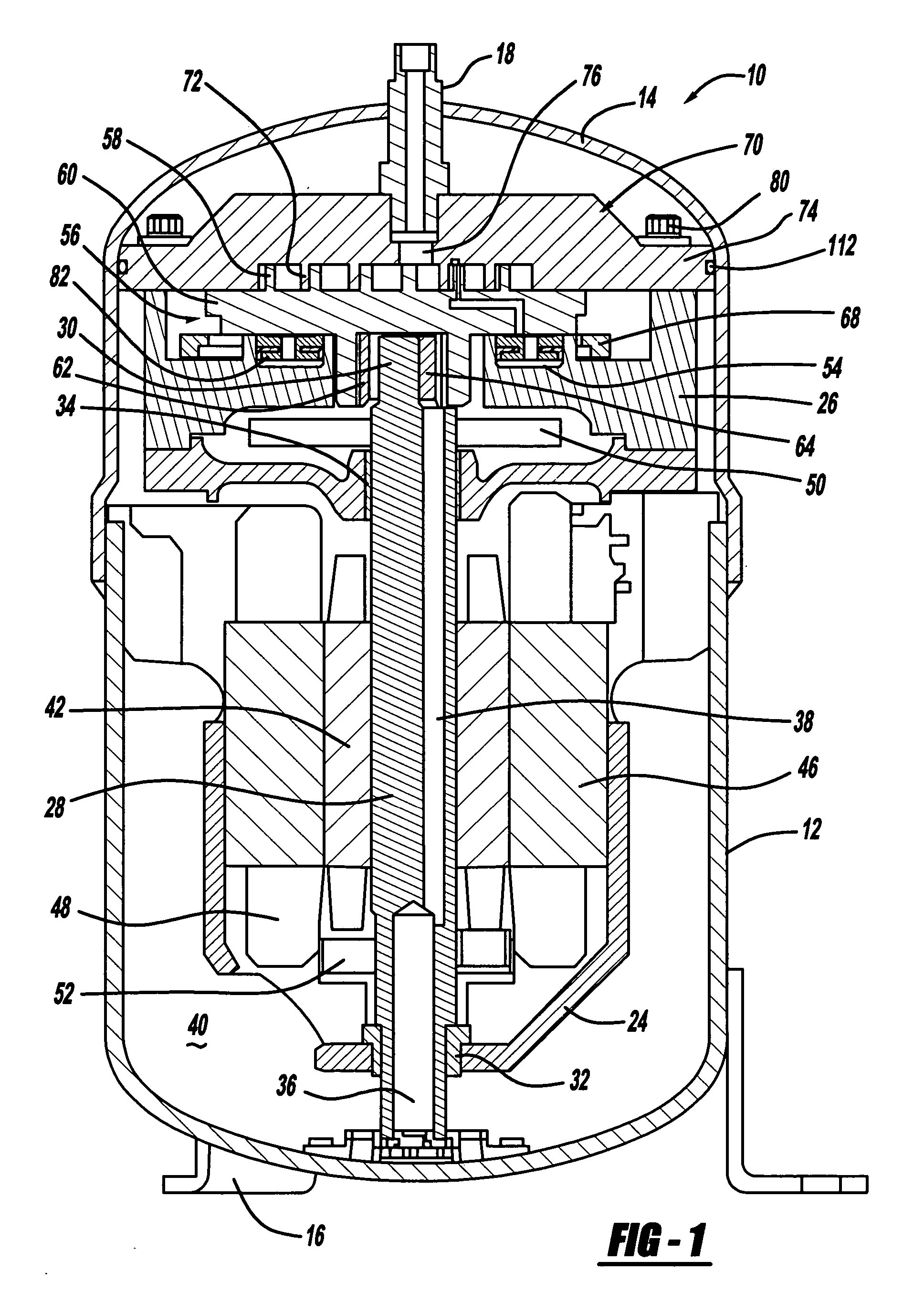
[0037] Referring now to the drawings in which like reference numerals designate like or corresponding parts throughout the several views, there is shown in FIG. 1 a scroll compressor in accordance with the present invention and which is designated generally by reference numeral 10. Compressor 10 comprises a generally cylindrical hermetic shell 12 having welded at the upper end thereof a cap 14 and at the lower end thereof a plurality of mounting feet 16. Cap 14 is provided with a refrigerant discharge fitting 18. Other major elements affixed to shell 12 include a lower bearing housing 24 that is suitably secured to shell 12 and a two piece upper bearing housing 26 suitably secured to lower bearing housing 24.

[0038] A drive shaft or crankshaft 28 having an eccentric crank pin 30 at the upper end thereof is rotatably...


PUM


Abstract

A scroll compressor has a fluid pressure biasing system for both the orbiting scroll member and the non-orbiting scroll member. The biasing system can utilize a pressurized gas from the pocket of the scroll compressor or it can utilize an external pressurized oil source. In an additional embodiment, a hydrostatic bearing is located between the orbiting scroll member and the non-orbiting scroll member.

Description

FIELD OF THE INVENTION [0001] The present invention is directed toward a high pressure scroll compressor. More particularly, the present invention is directed to a scroll machine which include biased scroll members to handle the high axial forces created in the high pressure scroll compressor. BACKGROUND AND SUMMARY OF THE INVENTION [0002] A class of machines exists in the art generally known as “scroll” machines for the displacement of various types of fluids. Such machines may be configured as an expander, a displacement engine, a pump, a compressor, etc., and the features of the present invention are applicable to any one of these machines. For purposes of illustration, however, the disclosed embodiments are in the form of a hermetic refrigerant compressor. [0003] Generally speaking, a scroll machine comprises two spiral scroll wraps of similar configuration, each mounted on a separate end plate to define a scroll member. The two scroll members are interfitted together with one o...

Claims


Application Information

Patent Timeline
IPC IPC(8): F04C2/00F04C18/00F03C4/00F01C1/02F03C2/00F01C1/063
CPCF04C18/0215F04C23/008Y10S418/01F04C29/02F04C2240/50F04C27/005F04C18/0253F04C18/0261F04C29/0007
Inventor IGNATIEV, KIRILL M.FOGT, JAMES F.AKEI, MASAO
Owner EMERSON CLIMATE TECH INC
Why Eureka
Try Eureka