Techniques for task management using presence
a task management and presence technology, applied in the field of task scheduling, can solve the problems of not allowing persons to perform several tasks at the same time interval, many task and calendaring systems are unable to discover or make use of actual current information,
- Summary
- Abstract
- Description
- Claims
- Application Information
AI Technical Summary
Problems solved by technology
Method used
Image
Examples
embodiment 352
[0077]FIG. 3B is a flow diagram that illustrates step 350 of the method 300 at a user monitor in more detail, according to an embodiment 352. That is, method 352 is a particular embodiment of step 350 in which data for the user data structure is determined for a particular person and published for use in method 550 described in more detail below with reference to FIG. 5B.
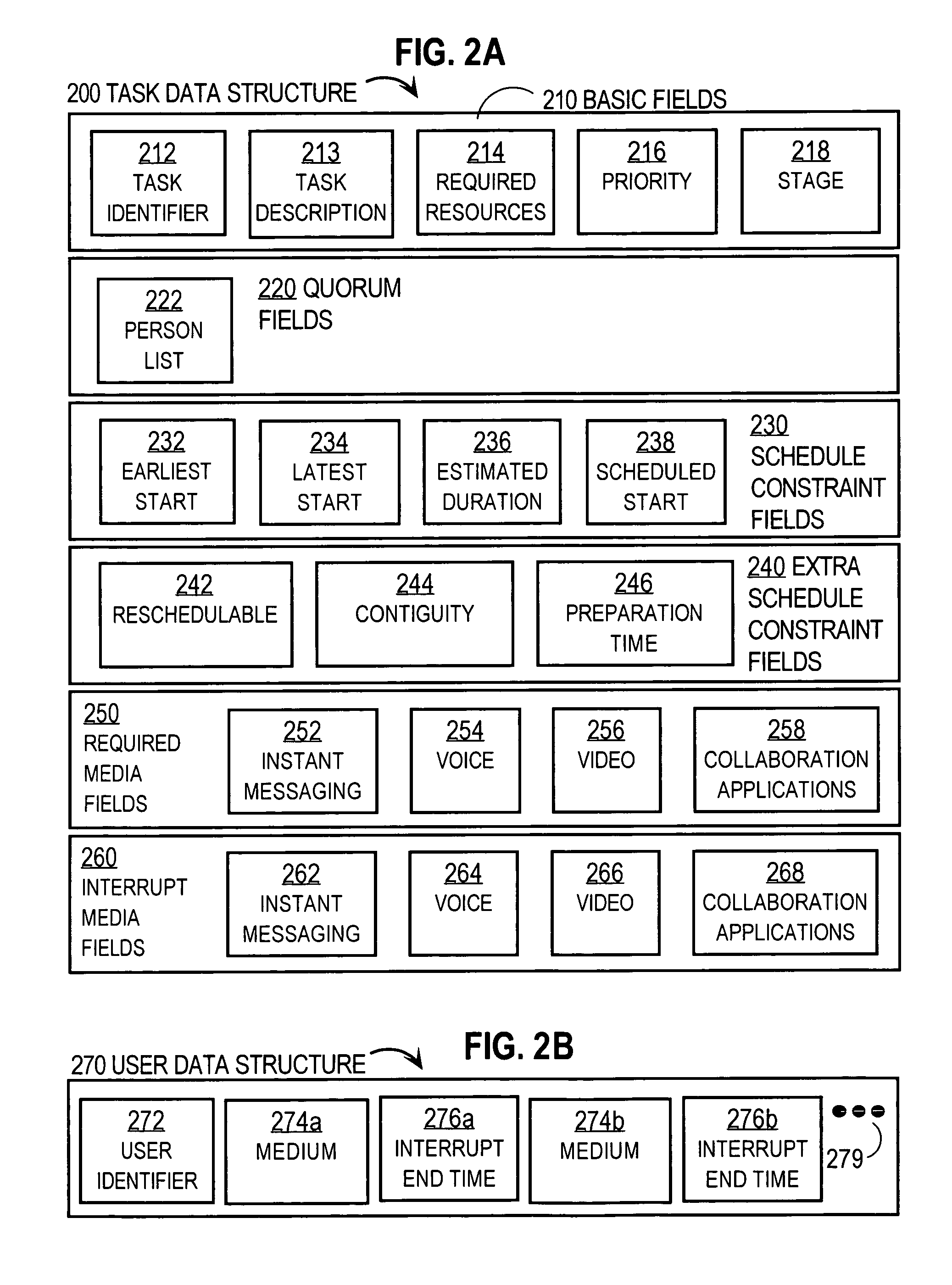
[0078] In step 354 an array of user interrupt end times, e.g. for fields 276, is initialized with large time values, e.g., end times hundreds of days from the current time. Such large time values indicate that each medium is interruptible for a task of any duration, i.e., there is an open time slot using this medium for a very long time.
[0079] In step 356 it is determined whether the person for whom the data is collected is executing a current task not yet considered, called here a “next” executing task. If the person is currently not executing any tasks, the result of step 356 is a negative. If every task the pers...
embodiment 500
[0106]FIG. 5A is a flow diagram that illustrates a step 430 of the method 400 of FIG. 3A for determining currently executable tasks and sorting the presence aware list, according to an embodiment 500. The steps of method 500 constitute a particular embodiment of step 430; in other embodiments of step 430 more, fewer or other steps, or some combination of changes, are used.
[0107] In step 510, the tasks in the list produced during step 410 are sorted first by category of schedulability (e.g., startable, re-schedulable, other) and then by priority. Thus all startable tasks are listed before all re-schedulable tasks that are not startable, which are listed before all other tasks. A task is startable if its earliest start time (e.g., as expressed by data stored in field 232) is at or before the current time, and its latest start time (e.g., as expressed in field 234) is at or after the current time. Within each category, for the illustrated embodiment, the tasks are listed in priority or...
embodiment 502
[0127] In embodiment 502, a value for a parameter DMAX is generated, representing the largest available timeslot duration (maximum duration) across all resources and participants. In some embodiments, the value for DMAX is expressed as a time stamp for the end of the period, similar to the way that the interrupt end times 276 are expressed. In the illustrated embodiment, DMAX is a duration as expressed as the difference between that timestamp and the current time.
[0128] In step 570, the value of DMAX is initialized to a large number, indicating infinite availability. Control then passes to step 572.
[0129] In step 572, the next resource to be processed is considered. If such a resource does not exist, control is passed to step 578. If another resource does exist, control is passed to step 574.
[0130] In step 574, it is determined whether the duration until the current resource stops being available is less than the value of DMAX. If the resource's available time is greater than or e...
PUM
 Abstract
Description
Claims
Application Information
 - R&D
- Intellectual Property
- Life Sciences
- Materials
- Tech Scout
- Unparalleled Data Quality
- Higher Quality Content
- 60% Fewer Hallucinations
Browse by: Latest US Patents, China's latest patents, Technical Efficacy Thesaurus, Application Domain, Technology Topic, Popular Technical Reports.
© 2025 PatSnap. All rights reserved.Legal|Privacy policy|Modern Slavery Act Transparency Statement|Sitemap|About US| Contact US: help@patsnap.com


