Modular flooring assemblies

Active Publication Date: 2007-05-03
COMC
View PDF20 Cites 63 Cited by
  • Summary
  • Abstract
  • Description
  • Claims
  • Application Information

AI Technical Summary

Problems solved by technology

Installing a conventional tile floor is a complicated procedure requiring expertise and craftsmanship.
First, the existing flooring may have to be removed.
This process may require several hours or days of drying time, during which time the floor must not be used.
Some previous attempts at modular flooring have not been fully successful.
Some prior art modular flooring ass

Method used


Image

  • Modular flooring assemblies
  • Modular flooring assemblies
  • Modular flooring assemblies

Examples


Embodiment Construction

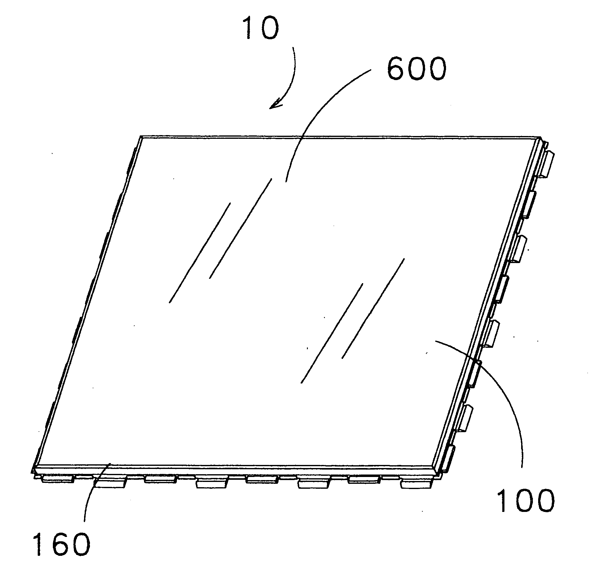
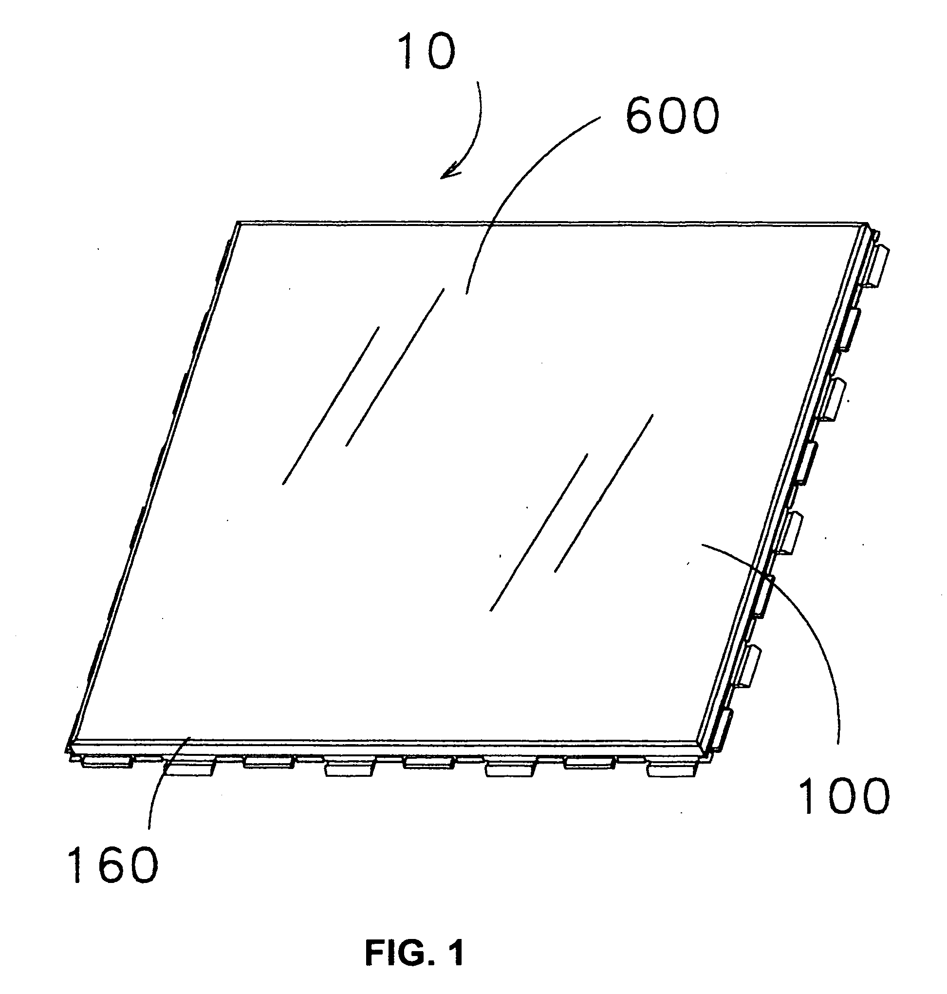
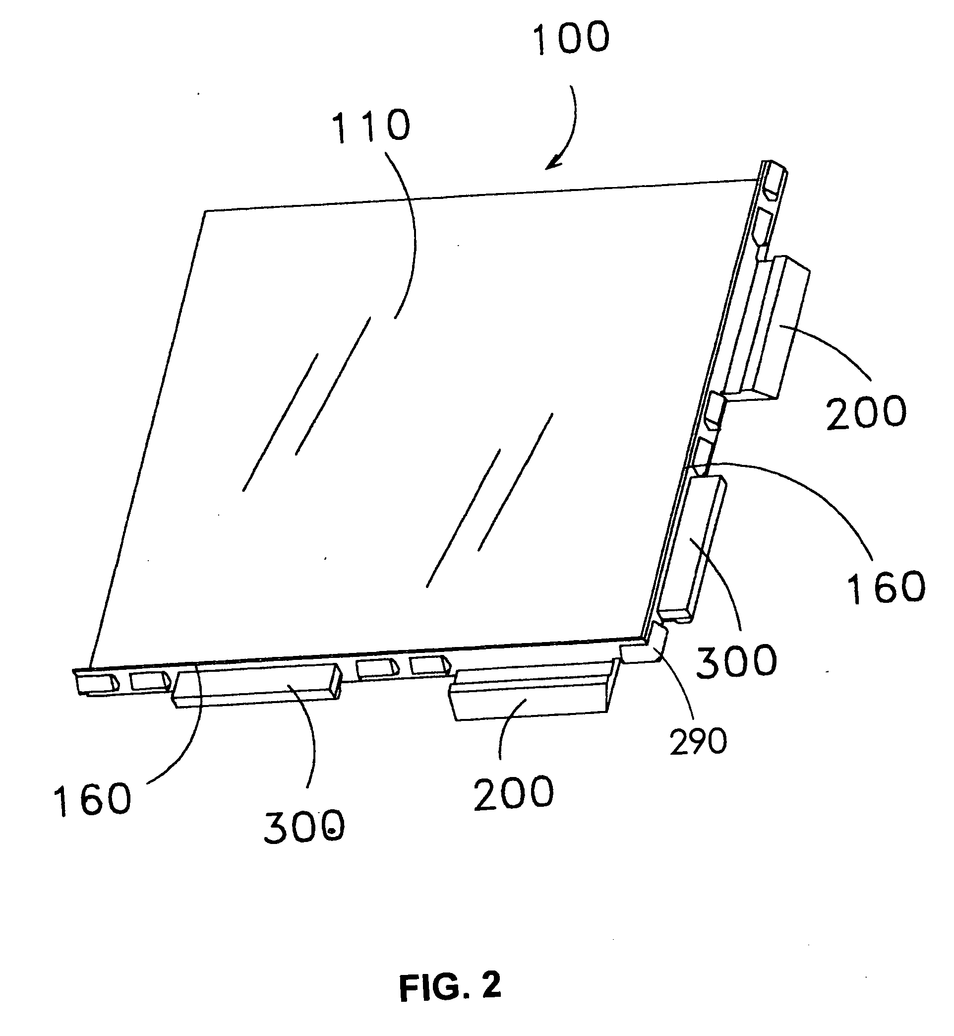
[0040] The present invention relates to a modular flooring assembly including a flooring component adhered to a tray substrate. The modular flooring assembly may be interconnected with additional modular flooring assemblies to form a modular floor suitable for most flooring applications. The flooring component may comprise tile or wood or other materials commonly used in flooring applications. The tray substrate comprises tabs, which provide for the tray substrates to interlock with tabs from an adjacent tray substrate. The fully assembled modular floor provides the appearance of a conventional floor. Fill-in grout or a snap-in grout may be used with the modular flooring assemblies. One suitable snap-in grout is a right angle grout member. The right angle grout member comprises inserts that are received by grout slots formed between the tabs.

[0041] Importantly, the modular floor may be assembled by individuals, who may lack the training and expertise to install a conventional floor...


PUM

PropertyMeasurementUnit
Angleaaaaaaaaaa
Angleaaaaaaaaaa
Shapeaaaaaaaaaa

Abstract

A modular flooring assembly including a flooring component adhered to a tray substrate is described. The modular flooring assembly may be interconnected with additional modular flooring assemblies to form a modular floor suitable for most flooring applications. The flooring component may be tile or wood or other materials commonly used in flooring applications. Convention fill-in grout or a snap-in grout may be used with the modular flooring assemblies. One suitable snap-in grout is a right angle grout member.

Description

[0001] This application claims priority to U.S. Provisional Patent Application No. 60 / 723,578 filed Oct. 4, 2005 and to U.S. Provisional Patent Application No. 60 / 733,686 filed Nov. 4, 2005.FIELD OF THE INVENTION [0002] The present invention relates to a modular flooring assembly including a flooring component adhered to a tray substrate. BACKGROUND OF THE INVENTION [0003] Installing a conventional tile floor is a complicated procedure requiring expertise and craftsmanship. First, the existing flooring may have to be removed. Next, a concrete backer board is attached to the sub floor using permanent fixing means, such as screws or nails. Then, a grout compound is applied to the backer board. Tiles must then be immediately and precisely laid on the grout compound. After the grout on the backer board holding the tiles is hardened, additional grout must be applied between the tiles. This process may require several hours or days of drying time, during which time the floor must not be u...

Claims


Application Information

Patent Timeline
IPC IPC(8): E04F13/08
CPCE04F15/02E04F15/02005E04F2201/0115E04F15/22E04F15/02044E04F15/0215E04F2201/026E04F15/02016E04F15/02194E04F15/082E04F15/203E04F15/02405
Inventor MCINTOSH, JONATHANSPERLING, NICOLE C.
Owner COMC
Why Eureka
Try Eureka