Gas generator

a generator and gas technology, applied in the direction of electric fuzes, separation processes, explosives, etc., can solve the problems of weight, complexity, and the typical requirement of raw materials, and achieve the effect of enhancing the cooling and slag deposition/filtering ability and maximizing the efficiency of the baffle assembly

Inactive Publication Date: 2007-05-03
JOYSON SAFETY SYST ACQUISITION LLC
View PDF99 Cites 19 Cited by
  • Summary
  • Abstract
  • Description
  • Claims
  • Application Information

AI Technical Summary

Benefits of technology

[0003] The above-referenced concerns are resolved by a gas generator containing a novel cooling assembly. The cooling assembly includes a baffle assembly that maximizes the gas / contact area interface thereby enhancing the associated cooling and slag deposition / filtering ability. The gases produced upon combustion are shunted radially inwardly toward a second end of the inflator through at least one gas orifice, and then funneled into the baffle assembly located at the second end. The funneling action maximizes the efficiency of the baffle assembly by concentrating the gases at the entry to the baffle assembly. The gases are then forced through the baffle assembly and out the gas generator. The baffle assembly may also contain a filter if desired.

Problems solved by technology

When manufacturing gas generators for gas generating systems, an ongoing challenge includes providing adequate amounts of inflating gas while yet reducing the weight, complexity, and raw materials typically required.
Given the weight of a filter assembly often included with many gas generators, a correlating challenge therefore is to provide the same cooling capability while yet reducing the weight of the cooling assembly associated therewith.

Method used


Image

  • Gas generator
  • Gas generator
  • Gas generator

Examples


Embodiment Construction

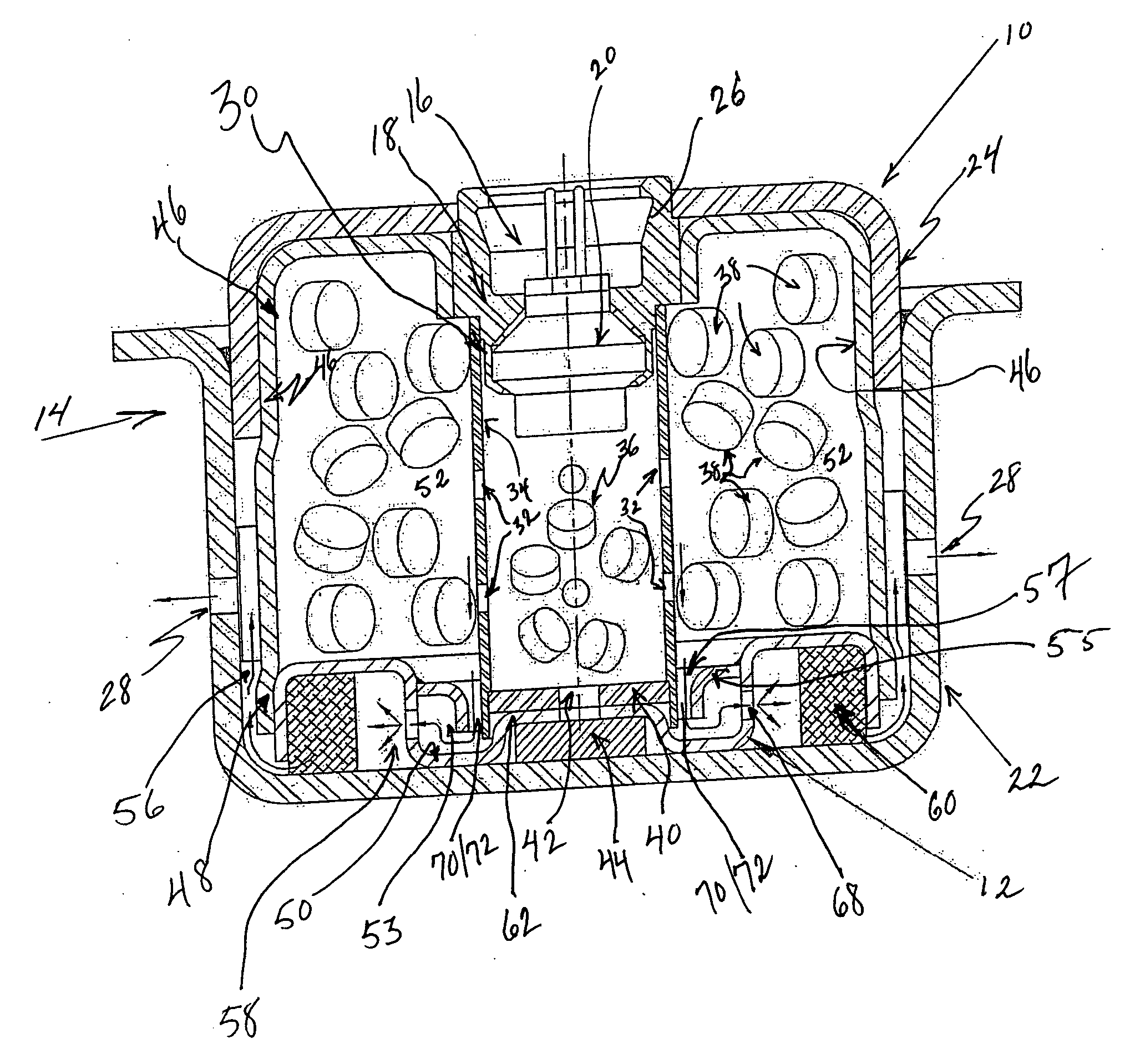
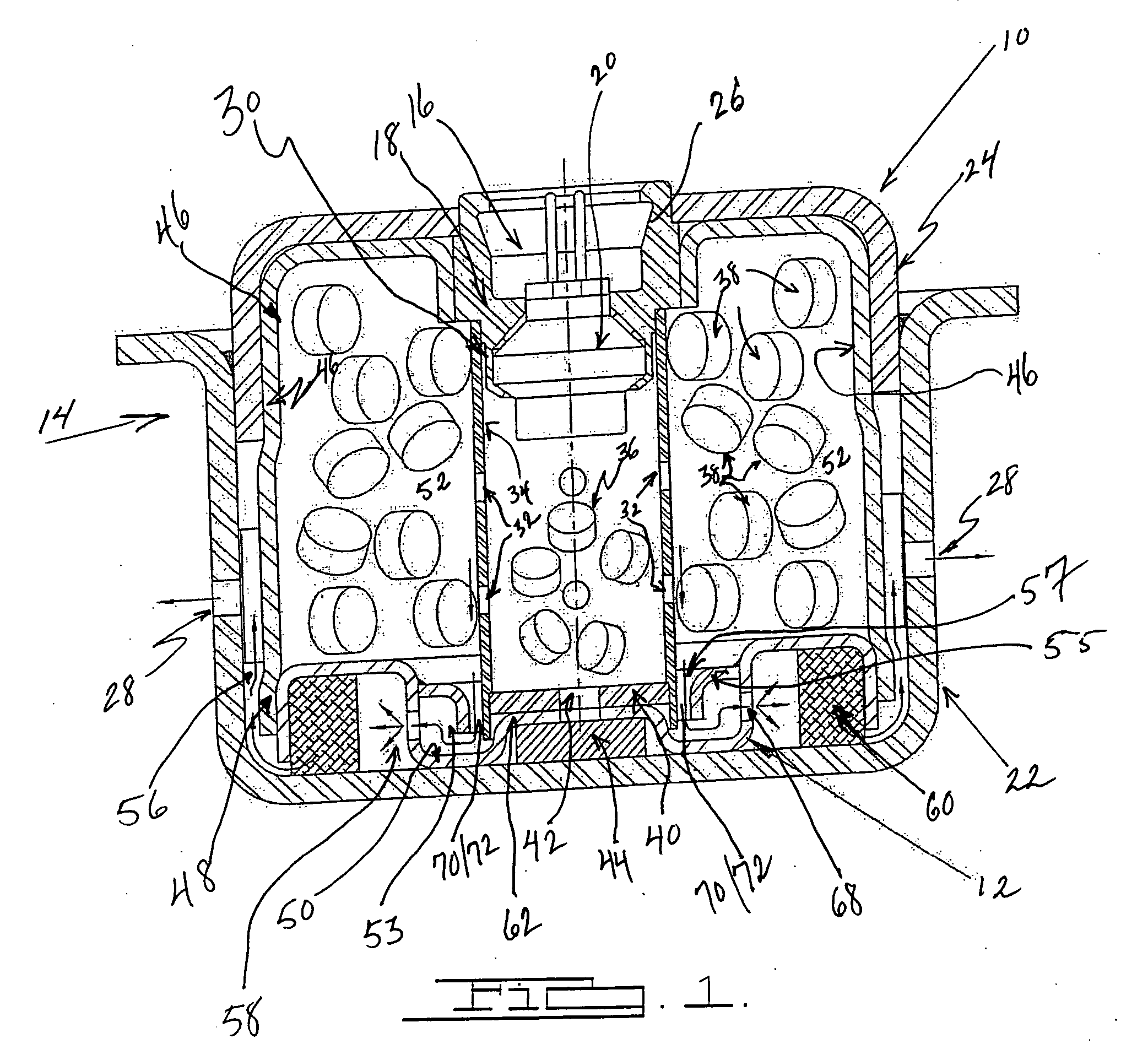
[0006] In accordance with the present invention, FIG. 1 illustrates a gas generator 10 incorporating a cooling system or baffle assembly 12 at an end of the gas generator 10. Gas generator 10 may, for example, be utilized to inflate a vehicle airbag.

[0007] As seen in FIG. 1, gas generator or inflator 10 includes a gas generator housing 14 formed by bonding, welding, or otherwise securing together a first housing portion 22 and a second housing portion 24 in a nested relationship. Second housing portion 24 contains an aperture 26 for receiving igniter assembly 16 therein. A plurality of gas discharge apertures 28 are spaced circumferentially around first housing portion 22 to enable fluid communication between an interior of housing 14 and an exterior of the housing. The first and second housing portions may be fabricated (for example, by stamping, casting, forming, or some other suitable process) from a rigid material such as carbon steel or stainless steel.

[0008] An igniter assem...


PUM

PropertyMeasurementUnit
volumeaaaaaaaaaa
weightaaaaaaaaaa
areaaaaaaaaaaa

Abstract

A gas generator 10 contains a baffle assembly for cooling of gases. An imperforate housing 46 is contained within the gas generator 10. A perforate housing 30 is contained within the imperforate housing 46. At least one orifice 70/72 is formed within the baffle assembly, where the orifice 70/72 is formed at the juncture 57 of the baffle assembly 12 and the perforate housing 30, at a second end of the perforate housing 30. Upon activation of the gas generator 10, gases produced are shunted through the orifice 70/72 and into the baffle assembly 12 for cooling and filtration thereof.

Description

CROSS REFERENCE TO RELATED APPLICATIONS [0001] This application claims the benefit of U.S. Application Ser. No. 60 / 732,569 having a filing date of Nov. 1, 2005.BACKGROUND OF THE INVENTION [0002] When manufacturing gas generators for gas generating systems, an ongoing challenge includes providing adequate amounts of inflating gas while yet reducing the weight, complexity, and raw materials typically required. Given the weight of a filter assembly often included with many gas generators, a correlating challenge therefore is to provide the same cooling capability while yet reducing the weight of the cooling assembly associated therewith. SUMMARY OF THE INVENTION [0003] The above-referenced concerns are resolved by a gas generator containing a novel cooling assembly. The cooling assembly includes a baffle assembly that maximizes the gas / contact area interface thereby enhancing the associated cooling and slag deposition / filtering ability. The gases produced upon combustion are shunted ra...

Claims


Application Information

Patent Timeline
Patent Type & Authority Applications(United States)
IPC IPC(8): B01D45/08
CPCB60R21/2644B60R2021/26011
Inventor QUIOC, EDUARDO L.
Owner JOYSON SAFETY SYST ACQUISITION LLC
Why Eureka
Try Eureka