Variable valve operating device

a valve operating device and variable valve technology, applied in the direction of valve details, valve arrangements, valve drives, etc., can solve the problems of increasing the cost of the case, not being able to achieve the ideal valve timing-lift characteristic, and not being able to achieve the change in the amount of valve timing required relative to the change in the valve lift amount required

Inactive Publication Date: 2007-05-03
TOYOTA JIDOSHA KK
View PDF2 Cites 11 Cited by
  • Summary
  • Abstract
  • Description
  • Claims
  • Application Information

AI Technical Summary

Benefits of technology

[0040] According to the eleventh aspect of the present invention, when the second swing member is interlocked with the aforementioned swing member, the operating characteristic of the second valve relative to the rotation of the camshaft can be continuously variable in accordance with the rotation amount of the control shaft. When the second swing member is interlocked with the third swing ...

Problems solved by technology

There is therefore a likelihood that an amount of change in the valve timing required relative to the change in the valve lift amount required will not be achiev...

Method used


Image

  • Variable valve operating device
  • Variable valve operating device
  • Variable valve operating device

Examples


first embodiment

[0066] A first embodiment of the present invention will be described below with reference to FIGS. 1 through 15.

[Configuration of the Variable Valve Operating Device According to the First Embodiment]

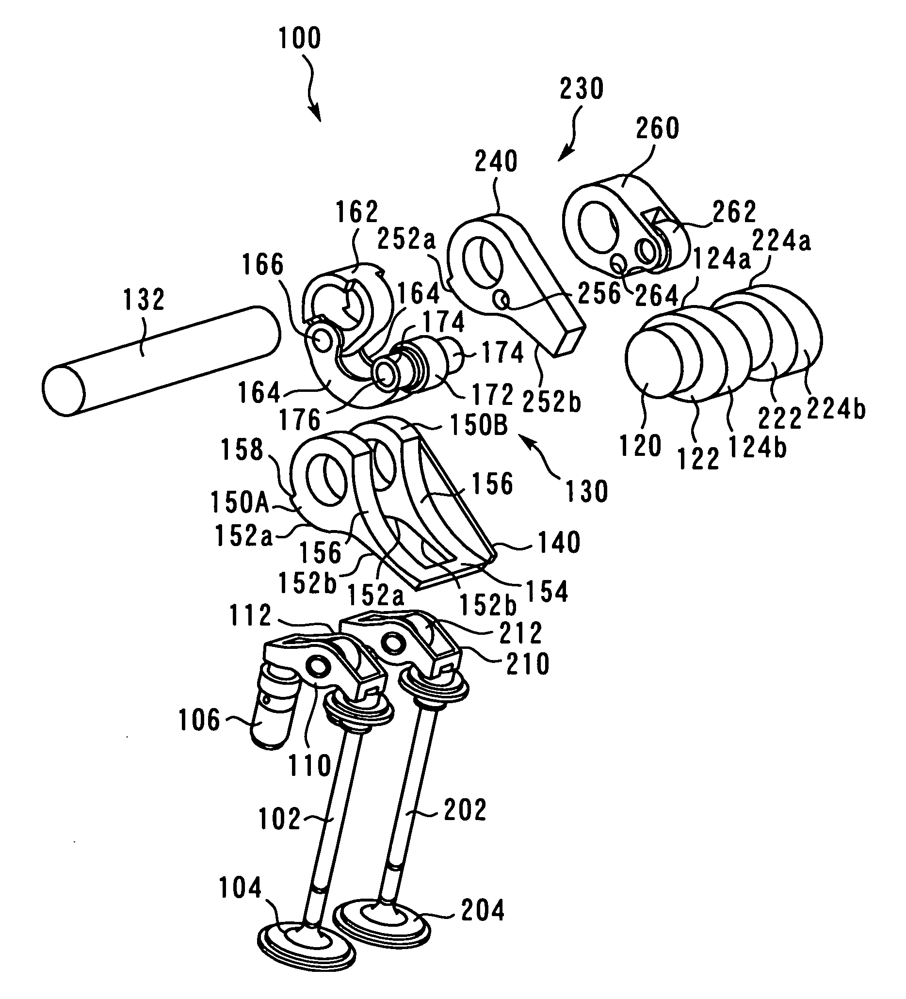
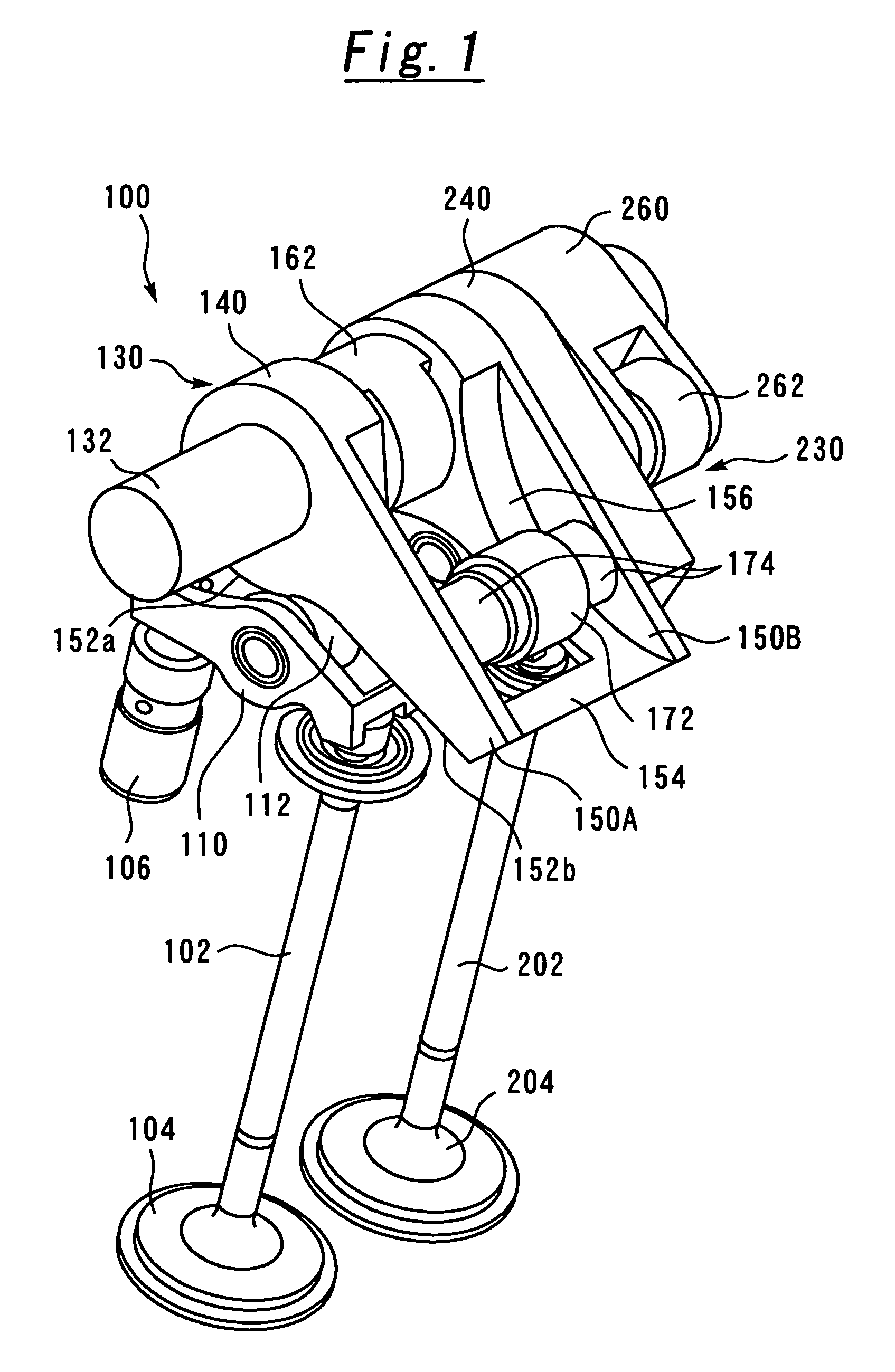
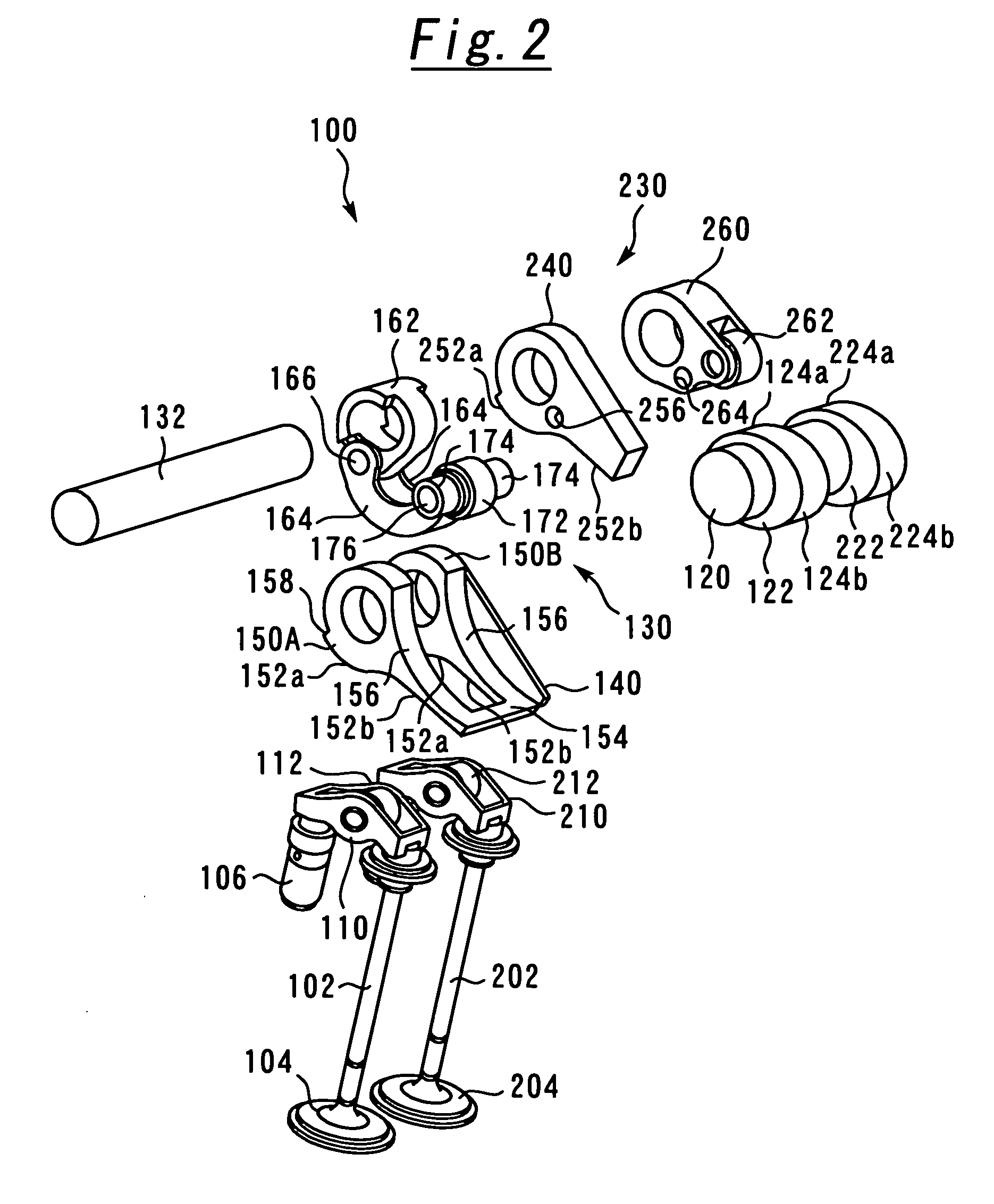
[0067]FIG. 1 is a perspective view showing the configuration of a variable valve operating device 100 according to the first embodiment of the present invention. FIG. 2 is an exploded perspective view showing the configuration of the variable valve operating device 100. FIG. 3 is a front view showing schematically the configuration of the variable valve operating device 100. The variable valve operating device 100 includes a mechanical valve operating mechanism of a rocker arm type. Rotation motion of a camshaft 120 is converted to a rocking motion of rocker arms (valve supporting members) 110, 210 by drive cams 122, 222 disposed on the camshaft 120. This is, in turn, converted to a lift motion in the vertical direction of valves 104, 204 supported by the rocker arms 110, 210, respect...

second embodiment

[0124] A second embodiment of the present invention will be described below with reference to FIGS. 16 through 19.

[Configuration of the Variable Valve Operating Device According to the Second Embodiment]

[0125]FIG. 16 is a perspective view showing the configuration of a variable valve operating device 300 according to the second embodiment of the present invention. FIG. 17 is a side elevational view seen in the direction of A in FIG. 16. This variable valve operating device 300 includes a mechanical valve operating mechanism of a rocker arm type. Rotation motion of a camshaft 320 is converted to a rocking motion of a rocker arm (valve supporting member) 310 by a drive cam 322 disposed on the camshaft 320. This is, in turn, converted to a lift motion in the vertical direction of a valve 304 supported by the rocker arm 310.

[0126] As in the first embodiment, the variable valve operating device 300 has an adjustment mechanism 330 interposed between the drive cam 322 and the rocker arm...

third embodiment

[0151] A third embodiment of the present invention will be described below with reference to FIGS. 20 through 22.

[Configuration of the Variable Valve Operating Device According to the Third Embodiment]

[0152]FIG. 20 is a side elevational view showing the configuration of a variable valve operating device 400 according to the third embodiment of the present invention. This variable valve operating device 400 includes a mechanical valve operating mechanism of a rocker arm type. Rotation motion of a camshaft 420 is converted to a rocking motion of a rocker arm (valve supporting member) 410 by a drive cam 422 disposed on the camshaft 420. This is, in turn, converted to a lift motion in the vertical direction of a valve 404 supported by the rocker arm 410. The drive cam 422 includes two cam surfaces 424a, 424b having different profiles from each other. One of the two cam surfaces, a nonoperating surface 424a, is formed to keep a predetermined distance from the center of the camshaft 420...


PUM


Abstract

A variable valve operating device is provided that allows an ideal valve timing-lift characteristic to be realized by associating a change in a valve timing with a change in a valve lift amount. A rotation motion of a drive cam is transmitted to a slide surface of a swing member via an intermediate member. Positions of the intermediate member on the slide surface are varied in association with the rotation of a control shaft by an interlock mechanism. The slide surface is formed to be curved toward the drive cam so that the distance from the center of a camshaft increases toward the farthest point from the swing center of the swing member within the area which the intermediate member contacts from the nearest point from the swing center of the swing member within the area which the intermediate member contacts.

Description

TECHNICAL FIELD [0001] The present invention relates to a variable valve operating device for an internal combustion engine, and more particularly, to a variable valve operating device that allows the operating characteristic of a valve to be changed mechanically. BACKGROUND ART [0002] A conventional variable valve operating device is known, as disclosed, for example, in Japanese Patent Laid-open No. 2003-239712, in which the valve lift amount and valve timing are mechanically changed according to engine operating conditions. In the variable valve operating device (hereinafter referred to as prior art) disclosed in Japanese Patent Laid-open No. 2003-239712, a control arm is fixed to a control shaft disposed in parallel with a camshaft and one end portion of a follower is mounted on the control arm and allowed to swing freely. Further, a swing cam is mounted on the control shaft and allowed to swing freely. A rocker arm is pressed against a cam surface of the swing cam. A first rolle...

Claims


Application Information

Patent Timeline
IPC IPC(8): F01L1/34
CPCF01L1/08F01L1/185F01L1/2405F01L1/267F01L13/0026F01L13/0063F01L2013/0068F01L2105/00F01L2820/01F01L2305/00
Inventor TATENO, MANABUASADA, TOSHIAKIEZAKI, SHUICHI
Owner TOYOTA JIDOSHA KK
Why Eureka
Try Eureka