Ventilation air assembly

a technology of ventilation air and assembly, which is applied in the direction of ventilation systems, heating types, and separation processes, can solve the problems of not being mounted in an existing wall, affecting the efficiency of ventilation air flow exiting the ventilator, and affecting the efficiency of ventilation air flow, etc., and achieves the effects of simple and cost-efficient construction, easy access to filter changes, and simple structur

Inactive Publication Date: 2010-12-23
CAMFIL AB
View PDF6 Cites 7 Cited by
  • Summary
  • Abstract
  • Description
  • Claims
  • Application Information

AI Technical Summary

Benefits of technology

[0006]It is therefore an object of the present invention to provide an arrangement which alleviates at least some of the above-mentioned problems.
[0009]Due to the construction of the ventilation air assembly, the filter holding unit is mountable at a wall surface, which causes no substantive damage to the wall as compared to the mounting of the described prior art ventilator, which is integrated into a wall. The inlet of the filter holding unit can be brought into fluid connection with any desired ventilation air flow. Thus, the wall can be provided with one or several air channels, which have a size and location that causes as little damage to the wall as possible. Furthermore, due to the position of the filter holding unit at the wall surface and the construction of the control member, the ventilation air flow exiting the outlet is directed in a favourable direction, which is towards the space between the heater device and the wall surface. Thereby the ventilation air is heated before it enters the room, which reduces the risk for experiencing the ventilation air flow as draught, increases the comfort of the room, and reduces the heating costs.
[0021]According to one embodiment of the invention, the housing is provided with a filter exchange opening and with a closure member for closing the filter exchange opening. The filter opening extends at a front side of the filter housing along substantially the whole length of the filter. Thereby, the opening has such a size that the filter can be easily accessed for changing thereof. Filter changing is even more facilitated in an embodiment where the closure member is pivotable arranged at the housing. Thereby the closure member can easily be brought in position where the entire opening and the filter behind are exposed, while still being attached to the housing. Thus, the closure member needs not be put down when the filter is exchanged, which troublesome regarding larger filter holding units and which also relives the user of the trouble of aligning the closure member again for closing the opening after the filter has been exchanged.
[0022]According to one embodiment of the invention, the control member is formed as a pivotable arranged flap, the filter exchange opening is arranged at the front side of the housing and the front wall of the housing forms the closure member of the filter exchange opening, wherein the front wall / closure member is pivotable arranged at the housing. According to one such embodiment, the pivot axes of the flap and the front wall / closure member coincide. This embodiment is advantageous in that it provides a simple, cost efficient construction.
[0023]According to one embodiment of the invention, the housing of the filter holding unit is an elongated box extending horizontally along the wall surface and the filter is an elongated filter body extending horizontally in the housing. The housing can be produced from standardized profiles, for example aluminium profiles. Thus, the housing can be produced in a few standard lengths only, which are cut into the appropriate lengths prior mounting on the wall surface. Furthermore, aluminium profiles have the advantage that they can relatively easy be provided with different appealing surface structures. Consequently, the filter holding unit can easily be adapted to fit different conditions and preferences.

Problems solved by technology

A problem with this known ventilator is that it can not be mounted in an existing wall without having to cause extensive damage to the wall.
This has also the effect that it is complicated and time consuming to mount the ventilator.
Another problem with this known ventilator is that the ventilation air flow exiting the ventilator sometimes is experienced as draught.
A problem with this known device is that, if at all possible, it is cumbersome to mount the device after a heater device once has been installed.
Another problem is that an air duct has to be provided through the wall close to the device, which may not be a preferred location with regard to wall damages.

Method used


Image

  • Ventilation air assembly
  • Ventilation air assembly
  • Ventilation air assembly

Examples


Embodiment Construction

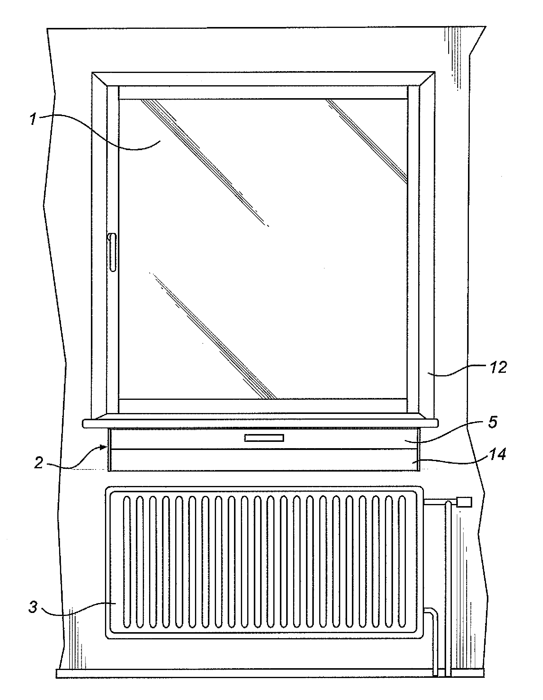
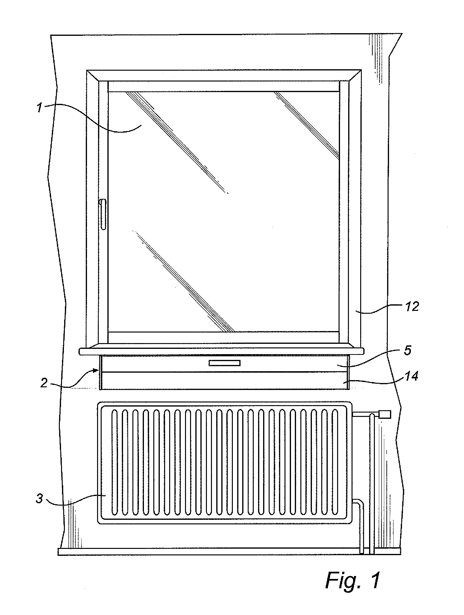
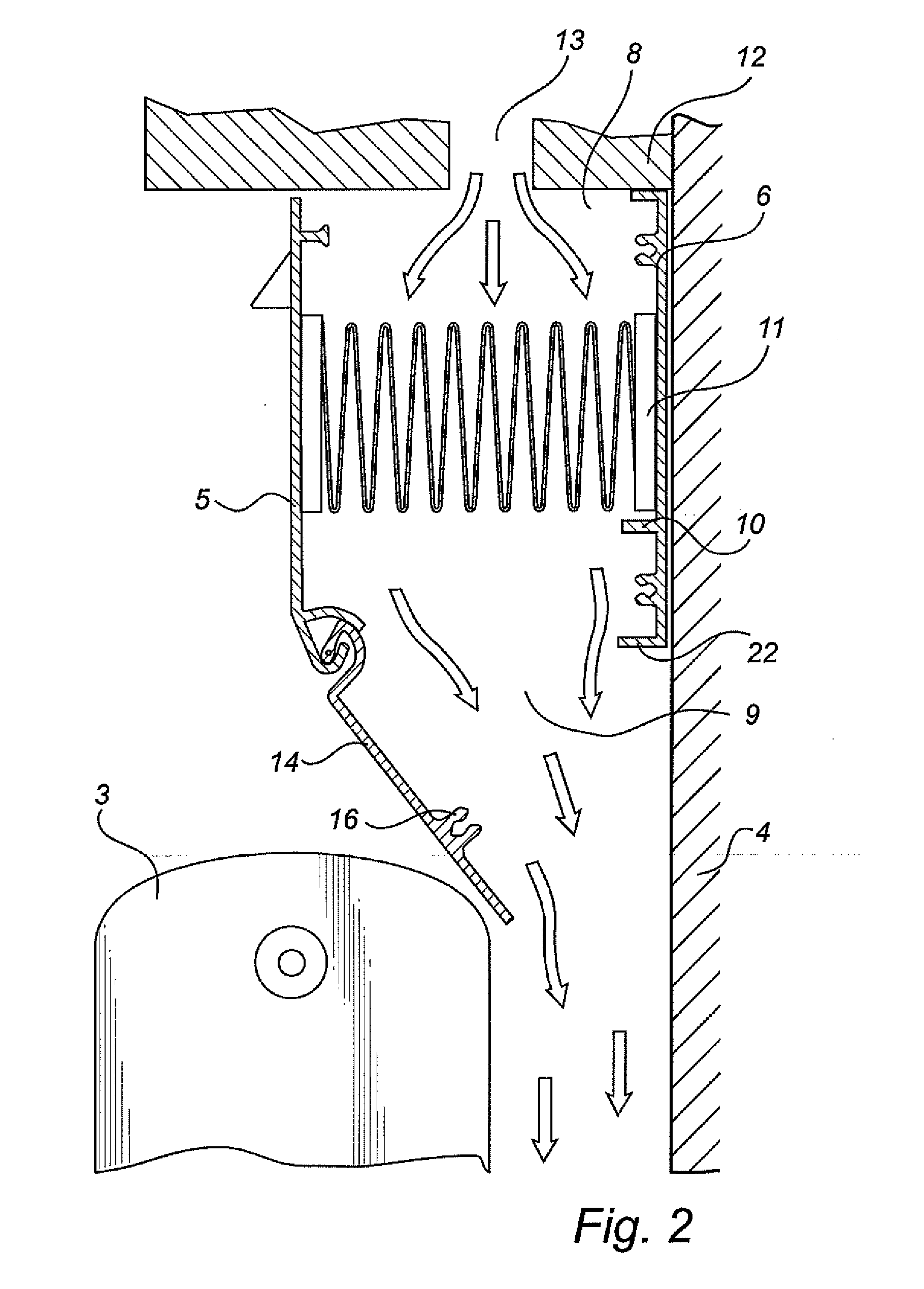
[0030]In FIGS. 1, 2 and 5 the general disposition of a ventilation air assembly and a filter holding unit according to an example embodiment is shown. The ventilation air assembly comprises a wall portion 4 with a window 1, a filter holding unit 2 and a heater device in form of a radiator 3. The filter holding unit 2 is mounted at a surface of the wall portion below and adjacent the window 1, wherein it extends horizontally along the wall. The radiator 3 is mounted below the filter holding unit 2.

[0031]The filter holding unit 2 comprises an elongated box-like housing, which is composed of aluminium profiles. Thus, the housing comprises a front wall 5, a back wall 6, and two side walls 7. The housing has an inlet 8 for ventilation air in form of an open top side and an outlet 9 for ventilation air in form of an open bottom side.

[0032]The housing is provided with a filter holding device, which comprises support edges 10 arranged at the back wall 6 and at the two side walls 7. An elong...


PUM

PropertyMeasurementUnit
volumeaaaaaaaaaa
lengthaaaaaaaaaa
timeaaaaaaaaaa

Abstract

One embodiment of the present invention relates to a ventilation air assembly, including a filter holding unit the filter holding unit includes a housing having an inlet for ventilation air and an outlet for ventilation air, and a control member for controlling a ventilation air flow through the outlet. The filter holding unit is mounted at the wall surface. Furthermore, the ventilation air assembly includes a filter, which is arranged in the housing of the filter holding unit such that the ventilation air passes through the filter when flowing through the housing from the inlet to the outlet. Furthermore, the ventilation air assembly includes a wall portion having a wall surface, and a heater device, such as a radiator, which is mounted at the wall surface. The filter holding unit and the heater device are such positioned relative each other and the wall surface, and the control member is such adjustable, that the ventilation air flow exiting the outlet is directed towards a space between the wall surface and the heater device. The embodiment of the present invention does also relate to a filter holding unit for use in such a ventilation air assembly.

Description

TECHNICAL FIELD OF THE INVENTION[0001]The present invention relates to a ventilation air assembly and to a filter holding unit for such a ventilation air assembly.BACKGROUND ART[0002]WO99 / 06775 discloses ventilator which is adapted to be placed adjacent a window in a wall. The ventilator is intended to be placed in a ventilation path between two sides of the widow or wall. The ventilator is an elongated device, which is mounted horizontally in the wall. Inside the ventilator, a barrier wall is arranged, which is provided with a series of apertures along the length thereof. A rotatable flap is pivotally mounted at the barrier wall, which flap can be pivoted between a position where the flap blocks airflow through the apertures, and a position where air is allowed to pass the flap and flow thorough the apertures. Before the barrier wall, as seen in the direction of the air flow through the ventilator, the ventilator comprises a weather hood. On the other side of the barrier wall, the ...

Claims


Application Information

Patent Timeline
Patent Type & Authority Applications(United States)
IPC IPC(8): E06B7/02F24F13/10B01D46/42
CPCE06B7/02F24F13/06F24D19/0085
Inventor LANS, ERIK
Owner CAMFIL AB
Why Eureka
Try Eureka