Surface treatment device

a surface treatment and device technology, applied in the direction of laser beam welding apparatus, manufacturing tools, welding/soldering/cutting articles, etc., can solve the problems of current mold machining technology facing difficulties in meeting demand, traditional mechanical machining methods and electrical discharge machining methods may not meet the surface roughness requirements of modern precision molds

Inactive Publication Date: 2007-05-03
HON HAI PRECISION IND CO LTD
View PDF15 Cites 12 Cited by
  • Summary
  • Abstract
  • Description
  • Claims
  • Application Information

AI Technical Summary

Benefits of technology

[0006] The typical polishing apparatus can be controlled to vibrate, and to achieve multi-angle polishing. However, the flexible element directly contacts with the surface to be polished in the polishing process. Therefore, the structure or size of the flexible element may directly affect the quality of polishing. In addition, it is very difficult to achieve satisfied polishing precision when the apparatus is used to polish a mold having fine and anomalous structures such as holes, grooves etc.

Problems solved by technology

With the increasing complexity and precision required in the manufacture of mold structures, current mold machining technologies are facing difficulties in meeting demand.
Traditional mechanical machining methods and electrical discharge machining methods may not meet surface roughness requirements of modern precision molds.
In the polishing process, a grinding material is positioned on the surface of the mold to be polished, and the flexible element is vibrated by amplified vibrations, thus creating friction between the mold surface to be polished and the grinding material.
Therefore, the structure or size of the flexible element may directly affect the quality of polishing.
In addition, it is very difficult to achieve satisfied polishing precision when the apparatus is used to polish a mold having fine and anomalous structures such as holes, grooves etc.

Method used


Image

  • Surface treatment device
  • Surface treatment device

Examples


Embodiment Construction

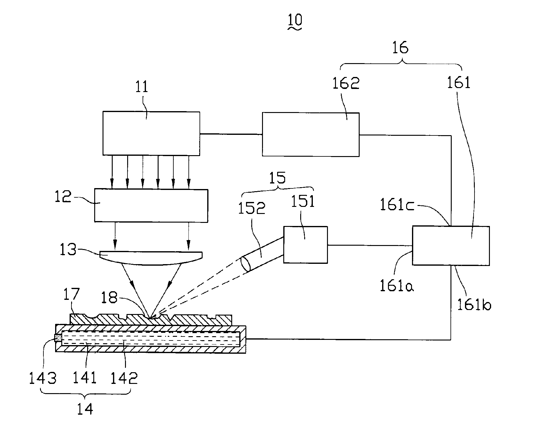
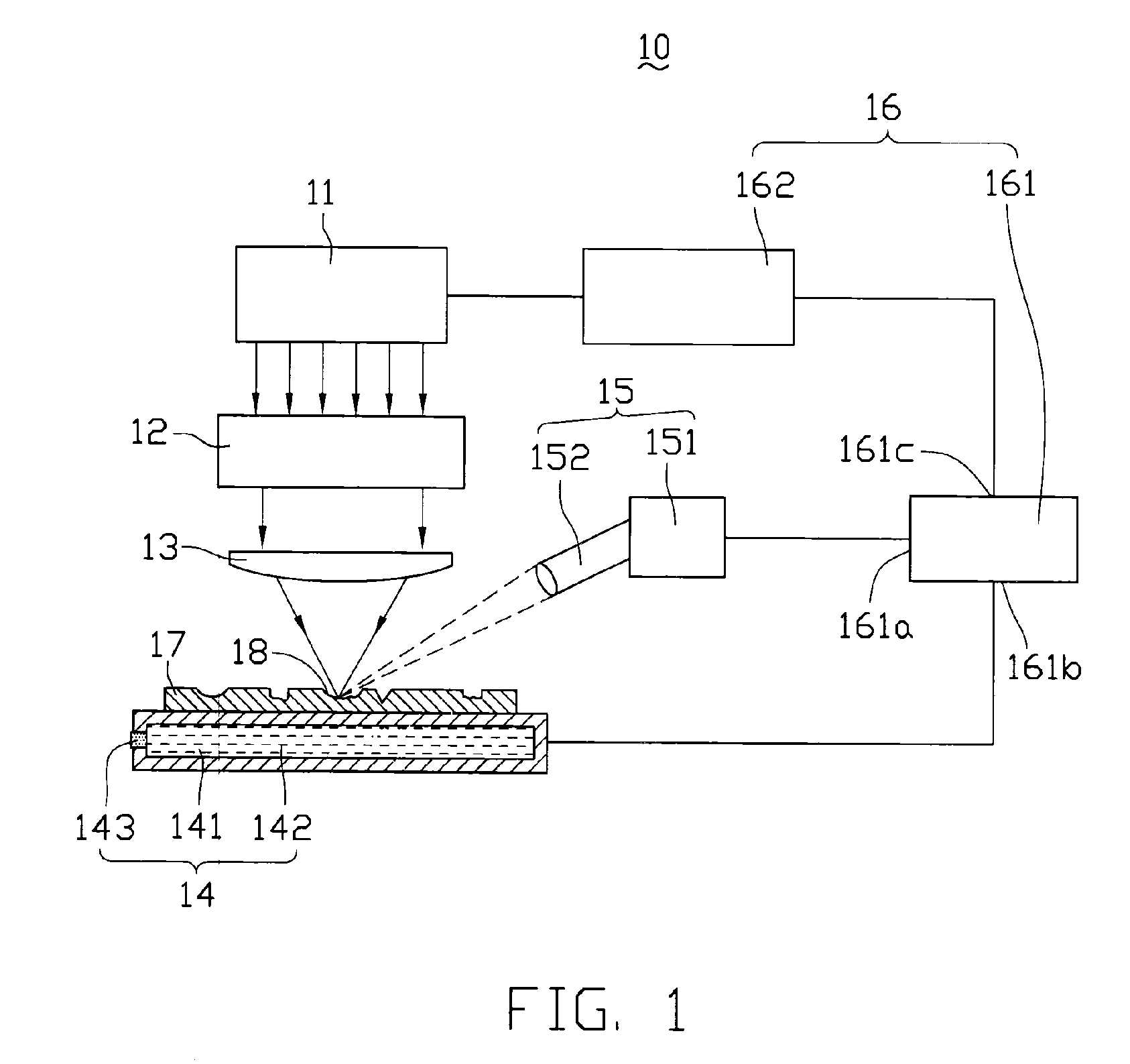
[0012] A mold machining apparatus for performing surface treatment, welding, cutting and other mold manufacturing processes is provided. Referring to FIG. 1, a surface treatment device 10 for treating surfaces of a mold is shown. The surface treatment device 10 includes a laser source 11, a focus lens 13, a working platform 14, a detector 15 and a controller 16. The laser source 11 is provided for emitting laser beams. The focus lens 13 is used to focus the laser beams from the laser source 11 to a spot for treating a workpiece to be machined. In order to advantageously focus the laser beams, a blocking shutter 12 is additionally provided. The blocking shutter 12 is positioned between the laser source 11 and the focus lens 13 for guiding laser beams to reach the focus lens 13. The working platform 14 is provided to support the workpiece to be machined, such as a mold 17 to be machined, and is positioned at an appropriate place what the focused laser beams can treat the mold 17. The ...


PUM

PropertyMeasurementUnit
wavelengthaaaaaaaaaa

Abstract

A surface treatment device includes a working platform, a laser source, a focus lens, a detector and a controller. The working platform is provided for supporting a workpiece thereon. The laser source is provided for producing laser beams. The focus lens is arranged between the working platform and the focus lens for focusing the laser beams to a spot for treating the workpiece. The detector is provided for detecting information of the spot and generating a feedback signal corresponding to the detected information. The controller is electrically connected with the laser source, the working platform and the detector and configured for receiving the feedback signal from the detector to control emitting of the laser beams of the laser source and movement of the working platform.

Description

DESCRIPTION [0001] 1. Technical Field [0002] The present invention generally relates to surface treatment devices, and more particularly to a device for treating surfaces of molds. [0003] 2. Description of the Related Art [0004] With the increasing complexity and precision required in the manufacture of mold structures, current mold machining technologies are facing difficulties in meeting demand. Traditional mechanical machining methods and electrical discharge machining methods may not meet surface roughness requirements of modern precision molds. [0005] A typical vibrating ultrasonic mold polishing apparatus is used to polish surfaces of a mold. The polishing apparatus includes an ultrasonic vibrator, an ultrasonic horn for amplifying vibrations, and a flexible element mounted on the ultrasonic horn for contacting with a surface of the mold to be polished. In the polishing process, a grinding material is positioned on the surface of the mold to be polished, and the flexible eleme...

Claims


Application Information

Patent Timeline
Patent Type & Authority Applications(United States)
IPC IPC(8): B23K26/00
CPCB23K26/0066B23K26/0009B23K26/0015B23K26/0018B23K26/0039B23K26/367B23K26/4005B23K26/4015B23K26/402B23K26/407B23K26/0006B23K26/40B23K26/364B23K26/352B23K2103/08B23K2103/10B23K2103/14B23K2103/15B23K2103/50
Inventor CHEN, GA-LANE
Owner HON HAI PRECISION IND CO LTD
Why Eureka
Try Eureka