Receiving circuit

a technology of receiving circuit and reference sensitivity, which is applied in the field of receiving circuit, can solve the problems of increasing current consumption and becoming difficult to achieve the reference sensitivity of 117 dbm, and achieve the effect of reducing size and low power consumption

Active Publication Date: 2010-10-12
RENESAS ELECTRONICS CORP
View PDF13 Cites 5 Cited by
  • Summary
  • Abstract
  • Description
  • Claims
  • Application Information

AI Technical Summary

Benefits of technology

[0010]And, in reception of bands I and VI, the adjacent blocking centered on 5 MHz can be suppressed sufficiently by setting the cutoff frequency low, but it may become difficult to achieve the reference sensitivity of −117 dBm due to degradation of the sensitivity at the filter. Therefore, it is desirable to set the cutoff frequency of the filter to be higher than frequencies at the reception of bands II to V.
[0012]Therefore, an object of the present invention is to provide a receiving circuit that is used for a cellular phone that is reduced in size and can realize low power consumption.
[0015]The present invention is a receiving circuit used in a cellular phone performing transmission and reception of a plurality of band wireless signals and includes a low-pass filter for removing blockers unnecessary for reception, wherein the low-pass filter is composed of a plurality of filters including a plurality of different circuit configurations and having different pole positions, and switching between a filter for blocker removal and a filter configuration with reduced sensitivity degradation is performed by combining a plurality of filters corresponding to received signal bands respectively, and power consumption is reduced by cutting power off unused filter portion in the filter configuration. By adopting filters so as to complementing their characteristics each other as the plurality of different filters, redundant filter configuration is not used, therefore, the area can be smaller to its necessity minimum, as a result, cost can be reduced.
[0017]According to the present invention, it is possible to provide a receiving circuit used in a cellular phone that is reduced in size and can realizes low power consumption by configuring a low-pass filter suitable for a reception band.

Problems solved by technology

But, in this operation, it is necessary to set the cutoff frequency of a low-pass filter near 1.92 MHz, that is the wanted frequency bandwidth, and adopt a special filter configuration in order to remove blockers, as a result, the special filter configuration may cause increase in current consumption.
And, in reception of bands I and VI, the adjacent blocking centered on 5 MHz can be suppressed sufficiently by setting the cutoff frequency low, but it may become difficult to achieve the reference sensitivity of −117 dBm due to degradation of the sensitivity at the filter.

Method used


Image

  • Receiving circuit
  • Receiving circuit
  • Receiving circuit

Examples


first embodiment

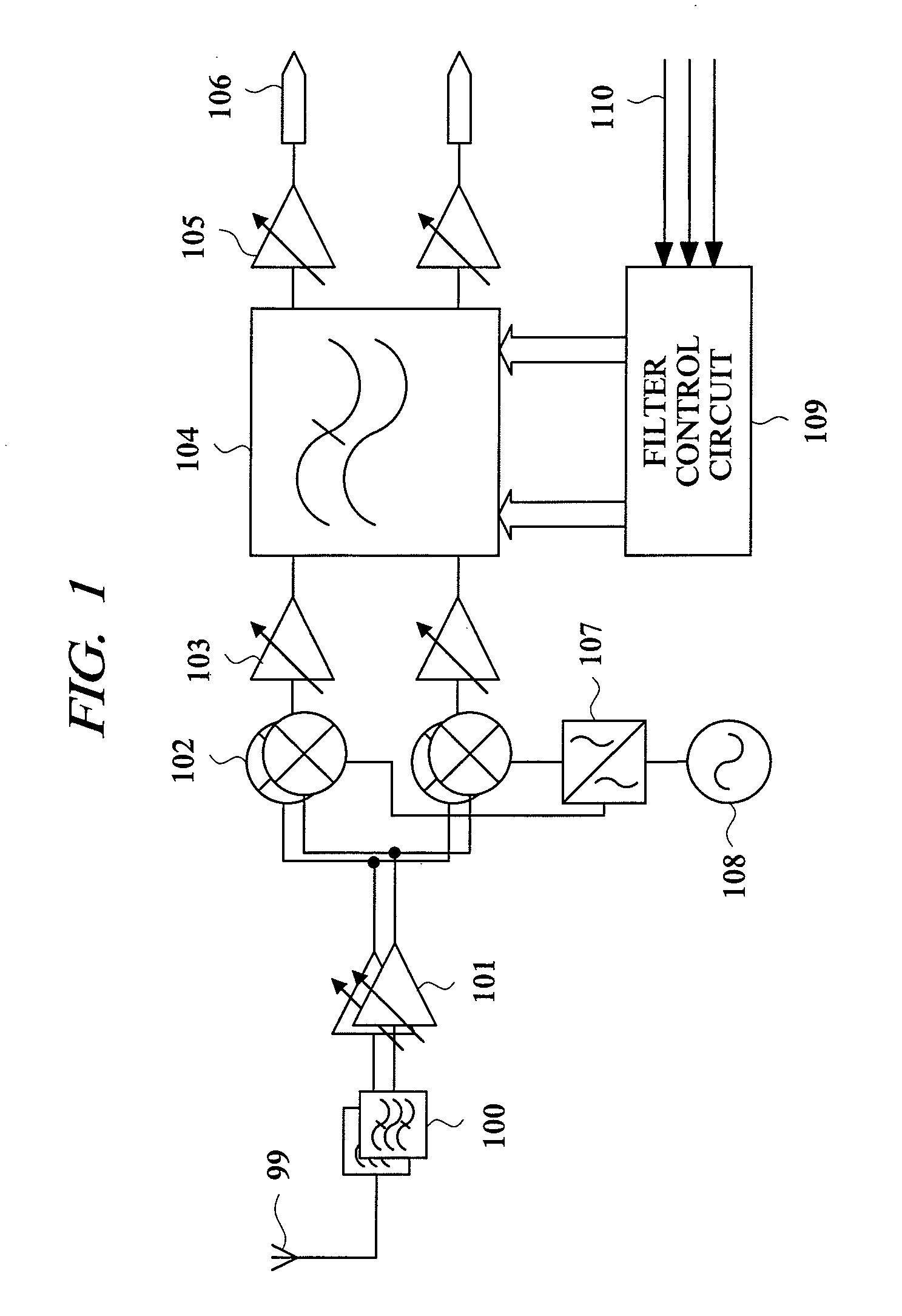
[0034]First, referring to FIG. 1, one example of a configuration and an operation of a receiving circuit in a first embodiment of the present invention will be explained. FIG. 1 shows a configuration of the receiving circuit in the first embodiment.

[0035]In FIG. 1, the receiving circuit in the embodiment is used in a cellular phone performing transmission and reception of a plurality of band wireless signals, and it is composed of an antenna input terminal 99, a band-pass filter 100, an LNA 101, a mixer 102, a first amplifier circuit 103, a low-pass filter 104, a second amplifier circuit 105, an output terminal 106, a 90-degree phase-shifting circuit 107, a local oscillator 108, a filter control circuit 109, and the like, and a band selection signal 110 is inputted into the filter control circuit 109.

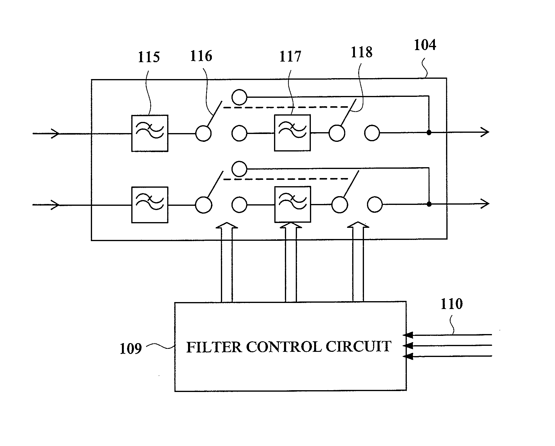
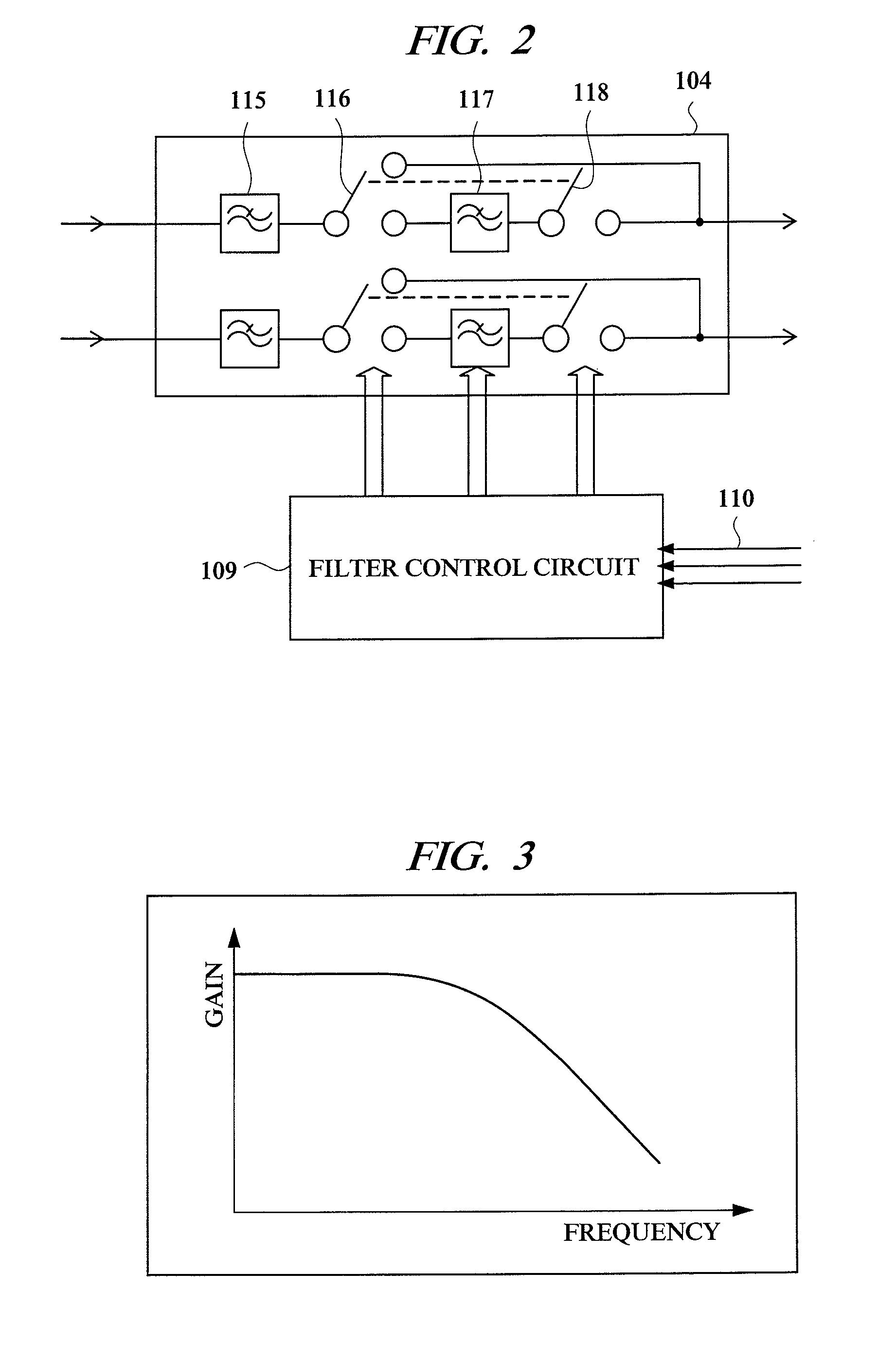
[0036]The receiving circuit is composed of mixers 102, first amplifier circuits 103, low-pass filters 104, second amplifier circuits 105, and output terminals 106, which are paired, res...

second embodiment

[0060]Referring to FIG. 9, one example of configuration and operation of a low-pass filter in a receiving circuit of a second embodiment of the present invention will be explained. FIG. 9 shows the configuration of the low-pass filter.

[0061]Since the receiving circuit in this embodiment is similar to that shown in FIG. 1 showing the first embodiment, detailed explanation thereof is omitted. Here, a tangible configuration example of a low-pass filter in a receiving circuit that can receive bands I and III of UMTS is shown.

[0062]In FIG. 9, a low-pass filter 104 in the embodiment is composed of a first switch 125, a first filter 126, a second filter 127, a second switch 128, and the like, and its different point from the first embodiment is that the first filter 126 and the second filter 127 are connected in parallel.

[0063]The first filter 126 is a filter used at a reception of band I and the second filter 127 is a filter used at a reception of band III. The first filter 126 is a filte...

third embodiment

[0069]Referring to FIG. 10, one example of configuration and operation of a low-pass filter in a receiving circuit of third embodiment of the present invention will be explained. FIG. 10 shows the configuration of the low-pass filter.

[0070]Since the receiving circuit in this embodiment is similar to that shown in FIG. 1 showing the first embodiment, detailed explanation thereof is omitted.

[0071]In the receiving circuits having the configurations of the first and second embodiments, in reception of bands I, II, and III signals of UMTS, there is a difference such that in reception of band II signal, an offset frequency of a blocker signal is 2.7 MHz, while in reception of band III signal, an offset frequency of a blocker signal is 2.8 MHz, so, by adopting a configuration that the notch frequency of the second filter constituting the low-pass filter 104 receiving band II and band III signals can be switched to the frequency of the blocker signal, a filter with a higher reference sensit...


PUM


Abstract

The present invention is a receiving circuit used for a cellular phone that is reduced in size and can realize low power consumption. In a signal reception circuit that is used in a cellular phone that perform transmission and reception of a plurality of band wireless signals and includes a low-pass filter for removing blockers unnecessary for signal reception, the low-pass filter 104 is composed of a plurality of filters composed of a plurality of different circuit configurations and having a plurality of different pole positions, switching between a filter for blocker removal and a filter configuration with reduced sensitivity degradation is performed by combining a plurality of filters for each signal reception band, and by performing power-off of an unnecessary filter portion in the filter configuration, power consumption is reduced. By constituting a plurality of different filters using filters mutually complementing their characteristics, a redundant filter configuration can be avoided, so that the area thereof can be suppressed to necessity minimum, and cost can be reduced.

Description

TECHNICAL FIELD[0001]The present invention relates to a cellular phone, and in particular, to an effective technique especially suitably applied to a receiving circuit that receives a plurality of band wireless signals.BACKGROUND ART[0002]Recently, in the middle of rising of a market of cellular phones applied with the third generation system superior in transmission characteristics to the second generation system according to advance of multimedia application of communication, further cost reduction, size reduction, and lower power consumption are strongly desired in development of the cellular phone. WCDMA (Wide band CDMA) system, one system for the mobile phone of the third generation is specified by 3GPP.[0003]According to a document “3GPP TS 25.101 Release 1999” (Non-Patent Document 1), bands I to II are allocated as UMTS (Universal Mobile Telecommunications System) frequency band. In a document “3GPP TS 25.101 Release5” (Non-Patent Document 2), band III is newly added, and sin...

Claims


Application Information

Patent Timeline
Patent Type & Authority Patents(United States)
IPC IPC(8): H04B1/10
CPCH04B1/1018
Inventor KATSUBE, YUSAKUYAMAMOTO, AKIO
Owner RENESAS ELECTRONICS CORP
Why Eureka
Try Eureka