Movable roof drive system

Inactive Publication Date: 2007-05-03
SPECIALTY VEHICLE ACQUISITION
View PDF43 Cites 1 Cited by
  • Summary
  • Abstract
  • Description
  • Claims
  • Application Information

AI Technical Summary

Benefits of technology

[0001] Movable members have been employed in automotive vehicles in a variety of locations. For example, movable members can include sunroof panels that are movable from a closed to an open position, full width roof panels movable between extended and retracted positions, pliable roof covers or roof covers having pliable portions, and the like. To move these movable members between positions, various mechanisms and/or structures can be used. These various mechanism

Problems solved by technology

These various mechanisms and/or structu

Method used


Image

  • Movable roof drive system
  • Movable roof drive system
  • Movable roof drive system

Examples


Example

[0011] The following description of the preferred embodiment is merely exemplary in nature and is in no way intended to limit the invention, its application, or uses.

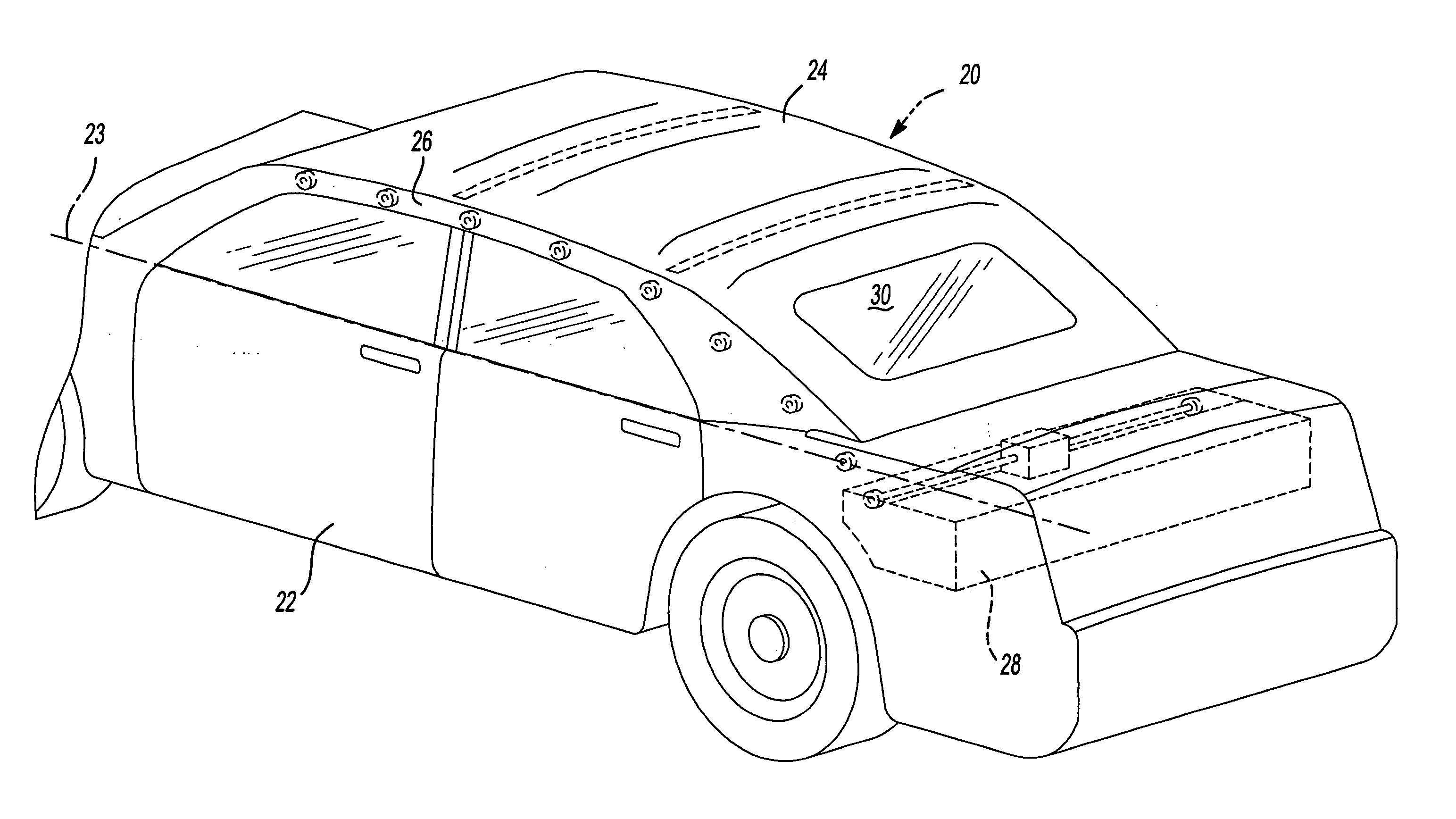
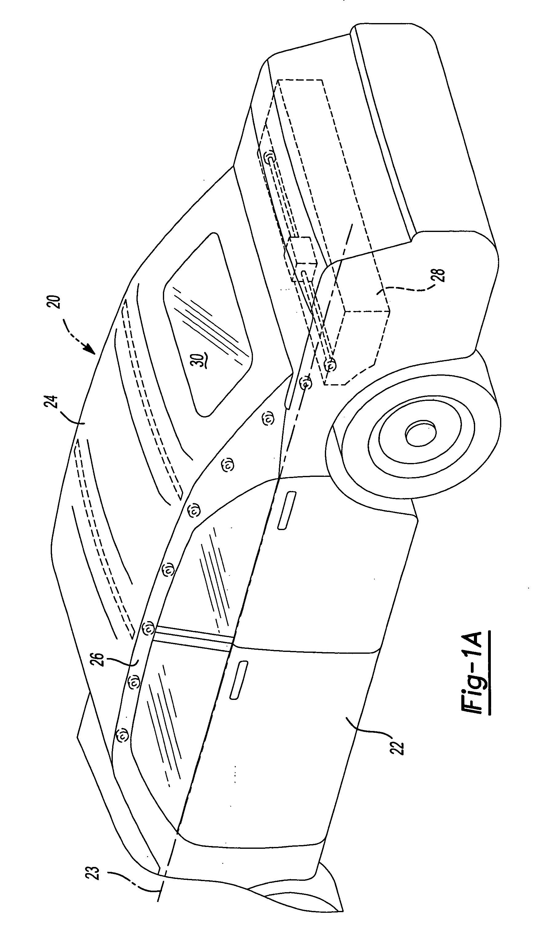
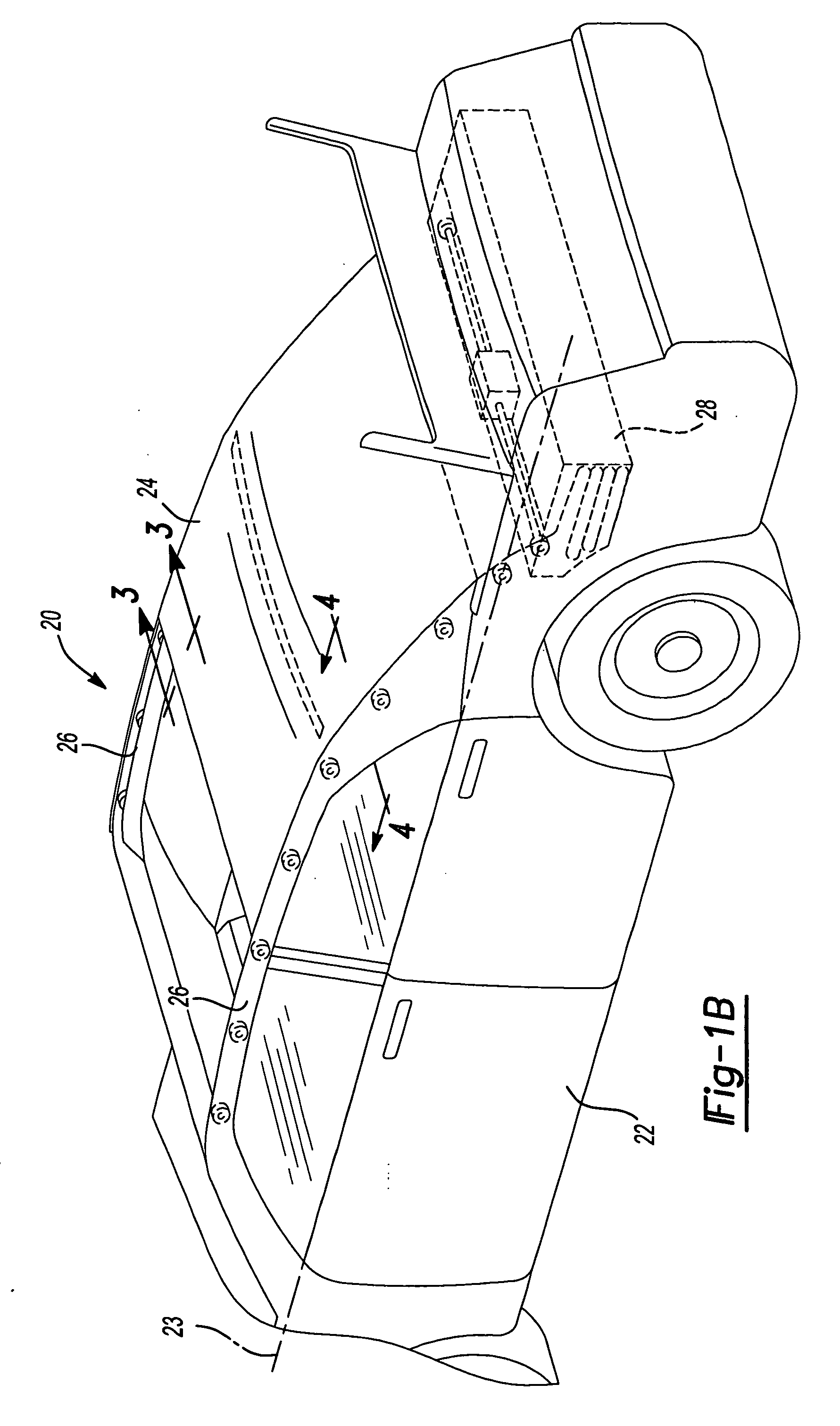
[0012] A movable roof drive system 20 according to the principles of the present invention is shown on an automotive vehicle 22 having a beltline 23 in FIGS. 1A-1C. Drive system 20 is operable to move a movable roof member 24 between two extreme positions. In the embodiment shown, movable roof member 24 is a soft-top roof that extends between fixed longitudinal roof rails 26. Drive system 20 moves roof 24 from a fully extended position, as shown in FIG. 1A, through intermediate positions, such as the position shown in FIG. 1B, to a retracted or stowed position below beltline 23, as shown in FIG. 1C. Roof 24 can be positioned at any location between the fully-extended position and the retracted position. Drive system 20 thereby enables roof 24 to be infinitely positioned between these two extreme positions.

[0013] Roof ...


PUM


Abstract

An automotive vehicle system includes a movable member and a belt-driven drive wheel that is operable to engage and disengage with the movable member and cause the movable member to move between positions. A tensioning member is operable to bias a movable roof member into contact with a wheel which is operable to engage with and selectively drive the roof member between positions.

Description

BACKGROUND AND SUMMARY OF THE INVENTION [0001] Movable members have been employed in automotive vehicles in a variety of locations. For example, movable members can include sunroof panels that are movable from a closed to an open position, full width roof panels movable between extended and retracted positions, pliable roof covers or roof covers having pliable portions, and the like. To move these movable members between positions, various mechanisms and / or structures can be used. These various mechanisms and / or structures may be complicated and / or expensive. Thus, it would be advantageous if a mechanism and / or structure could be employed that is of a lower cost and / or a simplified construction. It would be further advantageous if such a mechanism were capable of allowing infinite adjustment of the position of the movable member between extreme positions. Moreover, it would be advantageous if the power requirements to drive the mechanism are reduced or diminished. [0002] In accordan...

Claims


Application Information

Patent Timeline
IPC IPC(8): B60J7/06
CPCB60J7/061B60J7/067
Inventor MACNEE, ARTHUR L. IIITHEISEN, KURT
Owner SPECIALTY VEHICLE ACQUISITION
Why Eureka
Try Eureka