Low return loss rugged RFID antenna

a low-return loss, rugged technology, applied in the direction of burglar alarm by hand-portable article removal, burglar alarm mechanical actuation, instruments, etc., can solve the problems of increasing the requirements of rfid readers and difficulty in properly reading tags

Active Publication Date: 2007-05-03
SYMBOL TECH LLC
View PDF9 Cites 71 Cited by
  • Summary
  • Abstract
  • Description
  • Claims
  • Application Information

AI Technical Summary

Benefits of technology

[0014] These and other objects, advantages and features will become readily apparent in view of the following detailed description of the invention. Note that the Summary and Abstract sections may set forth one or more, but not all exemplary embodiments of the present invention as contemplated by the inventor(s).

Problems solved by technology

The requirements for RFID readers are becoming more difficult to meet.
Reflections due to these objects can create difficulties in properly reading the tags.
Furthermore, reading of tags often takes place in an environment where the reader antenna experiences physical abuse, such as in a warehouse environment, where objects may impact the reader antenna.

Method used


Image

  • Low return loss rugged RFID antenna
  • Low return loss rugged RFID antenna
  • Low return loss rugged RFID antenna

Examples


example rfid system embodiment

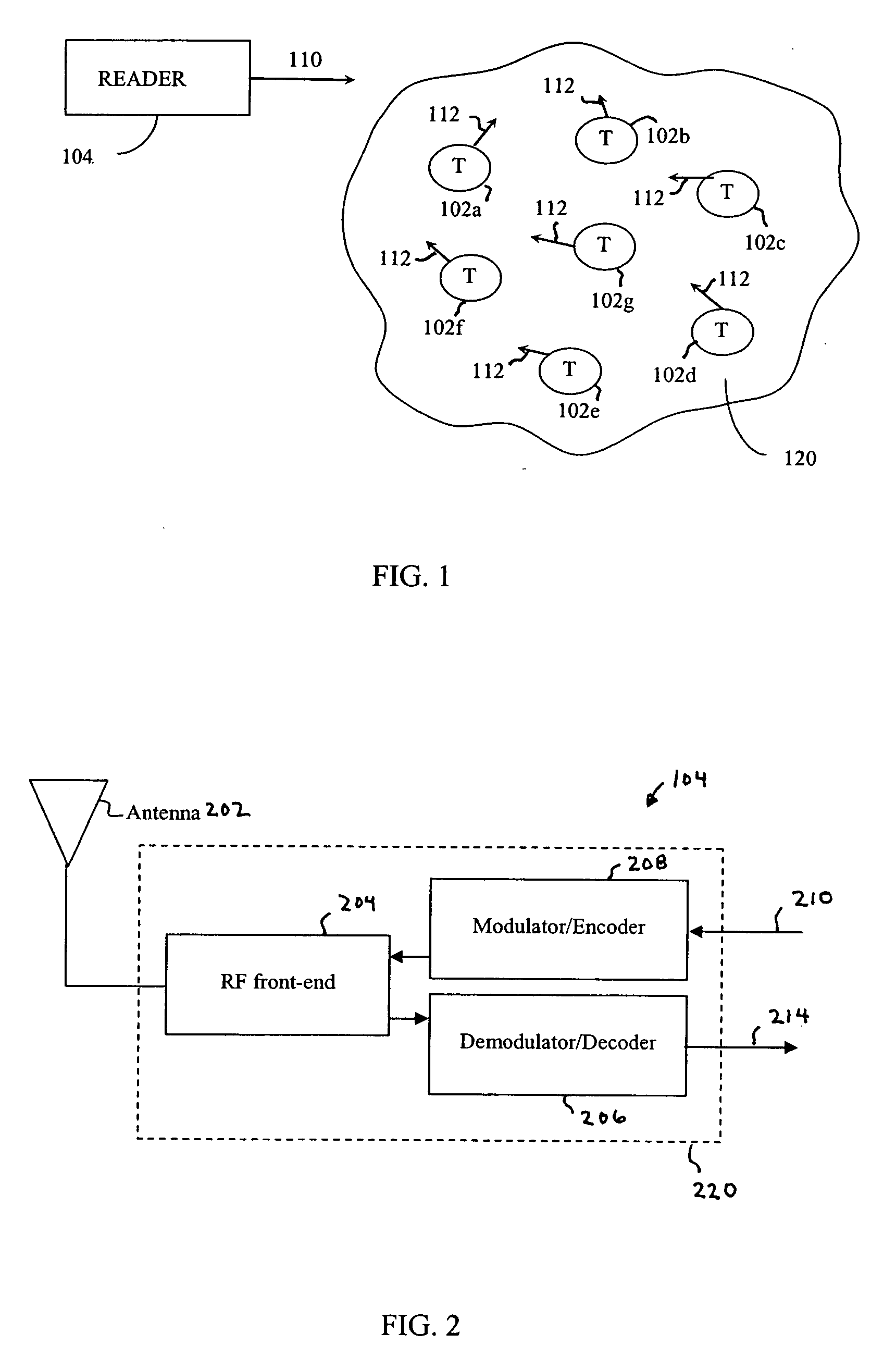
[0031] Before describing embodiments of the present invention in detail, it is helpful to describe an example RFID communications environment in which the invention may be implemented. FIG. 1 illustrates an environment 100 where RFID tag readers 104 communicate with an exemplary population 120 of RFID tags 102. As shown in FIG. 1, the population 120 of tags includes seven tags 102a-102g. A population 120 may include any number of tags 102.

[0032] Environment 100 includes one or more readers 104. A reader 104 may be requested by an external application to address the population of tags 120. Alternatively, reader 104 may have internal logic that initiates communication, or may have a trigger mechanism that an operator of reader 104a uses to initiate communication.

[0033] As shown in FIG. 1, reader 104 transmits an interrogation signal 110 having a carrier frequency to the population of tags 120. Reader 104 operates in one or more of the frequency bands allotted for this type of RF com...

example antenna structures

[0099]FIGS. 8-14 show views of example antenna structures and systems, according to embodiments of the present invention. In embodiments, the antenna structures of FIGS. 8-14 are used to implement antenna system 300 described above. The embodiments of FIGS. 8-14 are provided for illustrative purposes, and are not intended to limit the present invention. Alternative embodiments, including modifications, combinations, etc., will be known to persons skilled in the relevant art(s) from the teachings herein. These alternative embodiments are within the scope and spirit of the present invention.

[0100]FIG. 8 shows a cross-sectional view of an antenna assembly 800. As shown in FIG. 8, antenna assembly 800 includes a back plate 802, circuit board 400, antenna 420, a compressible electrically insulating material 808, and first and second compressible contact members 810 and 812.

[0101] Back plate 802 is a planar, rectangular shaped plate that provides mechanical support and protection for an...

example implementations

of Antennas Systems

[0146] Antenna systems of the present invention can be mounted anywhere that is convenient for interrogating RFID tags. For example, an antenna system can be mounted in a commercial environment, such as in a warehouse, a business, or store, and in a military or other non-commercial environment. Furthermore, an antenna system may be attached to a stationary structure or to a mobile structure. The antenna system may be used with fork lifts, warehouse box crushers, and with conveyor belts. The small size possible and the durability of the present antenna system enable the antenna system to be deployed in many previously inaccessible locations.

[0147] For example, FIGS. 16A and 16B show views of a forklift 1602 that mounts an antenna assembly 1604, according to an example embodiment of the present invention. Antenna assembly 1604 can be any of antenna assemblies 800, 900, 1000, and 1200 described above, for example. FIG. 16A shows a front view of forklift 1602, with f...


PUM


Abstract

Methods, systems, and apparatuses for RFID devices, such as reader antennas, are described. A reader antenna includes a quadrature hybrid coupler, a termination element, and an antenna, such as a patch antenna. The quadrature hybrid coupler has first, second, third, and fourth ports. The first port receives an input radio frequency RF signal. The second port outputs a first RF output signal. The third port outputs a second RF output signal. The second RF output signal is shifted in phase by 90 degrees relative to the first RF output signal. The fourth port is coupled to the termination element. The patch antenna has a first point coupled to the first RF output signal and a second point coupled to the second RF output signal. The patch antenna radiates a circularly polarized RF signal due to the received first and second RF output signals. The circularly polarized RF signal may be used to interrogate tags. Furthermore, the reader antenna is integrated into a ruggedized structure that provides environmental protection for the antenna, including providing shock absorption for impacts to the antenna.

Description

BACKGROUND OF THE INVENTION [0001] 1. Field of the Invention [0002] The invention relates to radio frequency identification (RFID) readers, and in particular, to RFID reader antennas. [0003] 2. Background Art [0004] Radio frequency identification (RFID) tags are electronic devices that may be affixed to items whose presence is to be detected and / or monitored. The presence of an RFID tag, and therefore the presence of the item to which the tag is affixed, may be checked and monitored wirelessly by devices known as “readers.” Readers typically have one or more antennas transmitting radio frequency signals to which tags respond. Since the reader “interrogates” RFID tags, and receives signals back from the tags in response to the interrogation, the reader is sometimes termed as “reader interrogator” or simply “interrogator”. [0005] With the maturation of RFID technology, efficient communication between tags and interrogators has become a key enabler in supply chain management, especiall...

Claims


Application Information

Patent Timeline
Patent Type & Authority Applications(United States)
IPC IPC(8): G08B13/14G06K19/06
CPCB66F9/0755G06K7/0008G06K7/10316H01Q1/2216H01Q9/0435
Inventor KNADLE, RICHARD T. JR.DURON, MARK
Owner SYMBOL TECH LLC
Why Eureka
Try Eureka