

Liquid crystal display and manufacturing method thereof
Patent Information
- Authority / Receiving Office
- US · United States
- Patent Type
- Applications(United States)
- Current Assignee / Owner
- TCL CHINA STAR OPTOELECTRONICS TECH CO LTD
- Publication Date
- 2007-05-03
Smart Images
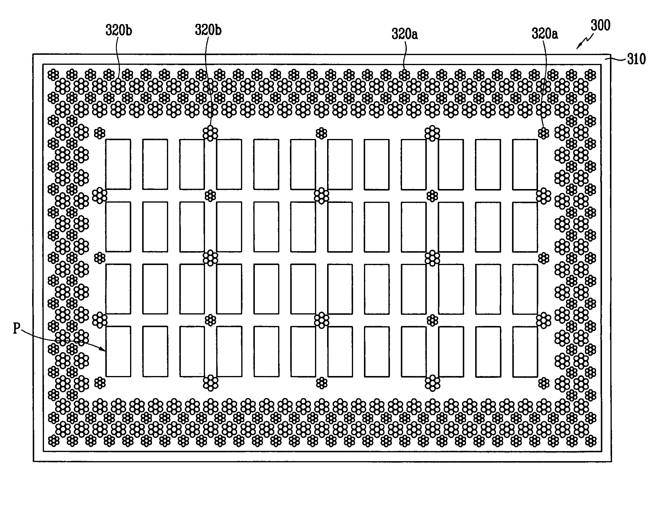
Figure 1 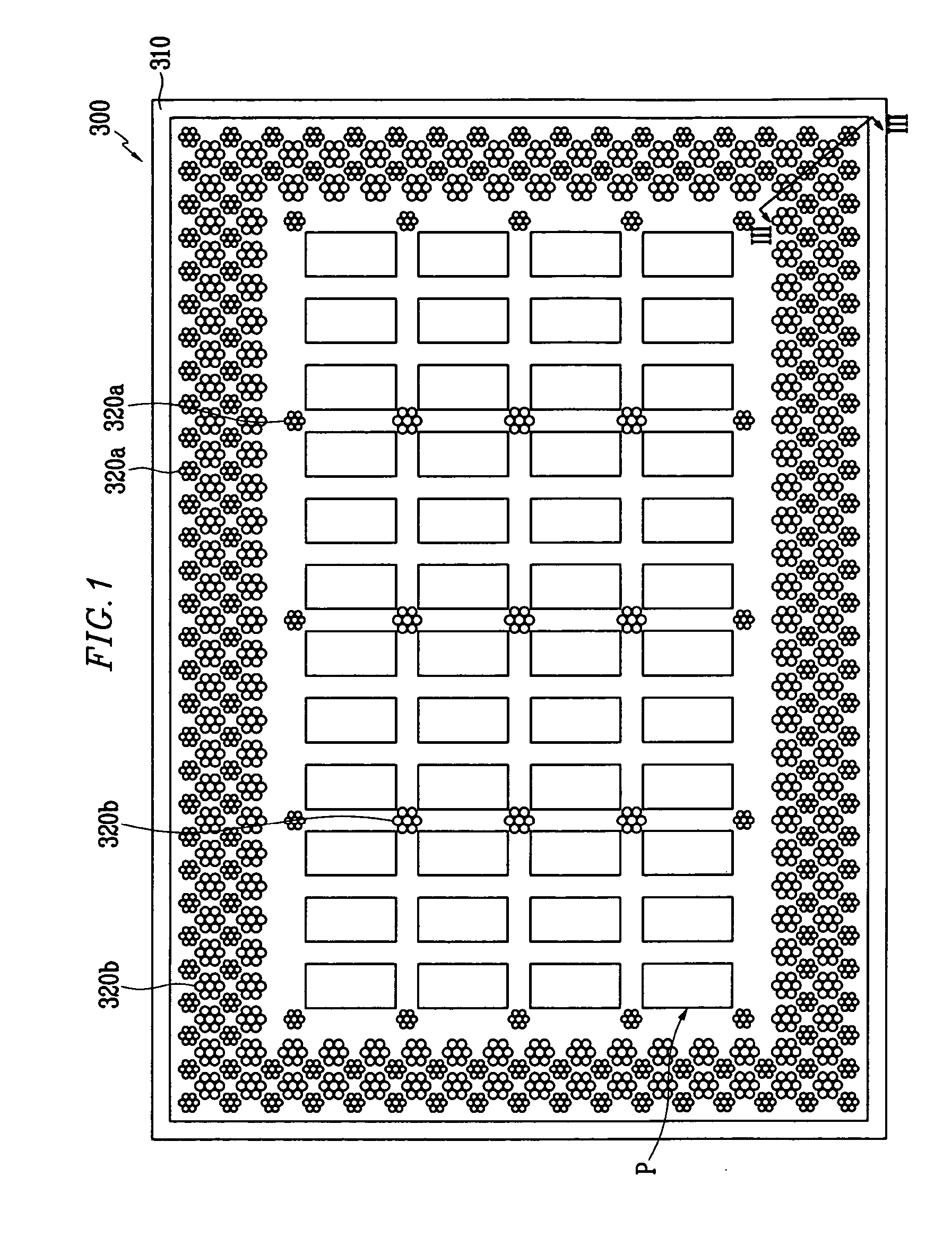
Figure 2 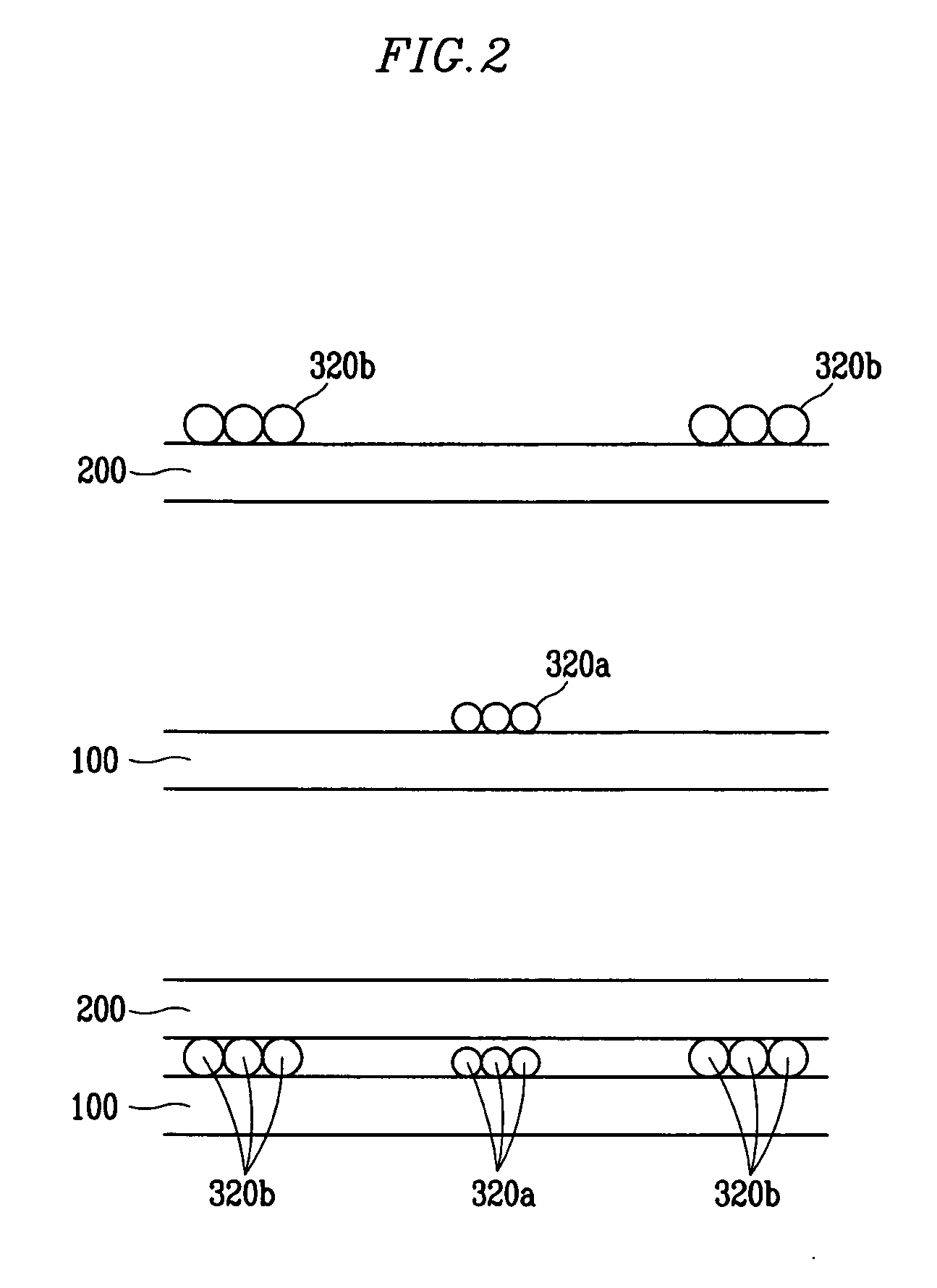
Figure 3
Abstract
Description
CROSS-REFERENCE TO RELATED PATENT APPLICATION
[0001] This application claims priority to Korean Patent Application Nos. 10-2005-0102363 filed on Oct. 28, 2005 and 10-2005-0133584 filed on Dec. 29, 2005, in the Korean Intellectual Propery Office, the disclosures of which are incorporated by reference herein in their entirety. BACKGROUND OF THE INVENTION
[0002] (a) Technical Field
[0003] The present disclosure relates to a liquid crystal display and a manufacturing method thereof.
[0004] (b) Discussion of the Related Art
[0005] A liquid crystal display (LCD) is one of the most widely used flat panel displays. An LCD includes two display panels provided with field-generating electrodes such as pixel electrodes and a common electrode, and a liquid crystal (LC) layer interposed therebetween. The LCD displays images by applying voltages to the field-generating electrodes to generate an electric field in the LC layer, which determines orientations of LC molecules in the LC layer to adjust ...