Image input system

Inactive Publication Date: 2007-05-03
CANON KK
View PDF33 Cites 25 Cited by
  • Summary
  • Abstract
  • Description
  • Claims
  • Application Information

AI Technical Summary

Benefits of technology

[0074] The camera control system and method of the present invention with the above arrangements can designate an imaging inhibited area and thereby protect the privacy of a user. Additionally, since the imaging inhibited area can be set in a map window, the operation is easy and the imaging inhibited area can be clearly designated.
[0075] Also, even if a direction in

Problems solved by technology

The following problem arises when further improvements of a camera control system of this sort are attempted.
However, persons in the sensing

Method used


Image

  • Image input system
  • Image input system
  • Image input system

Examples


first embodiment

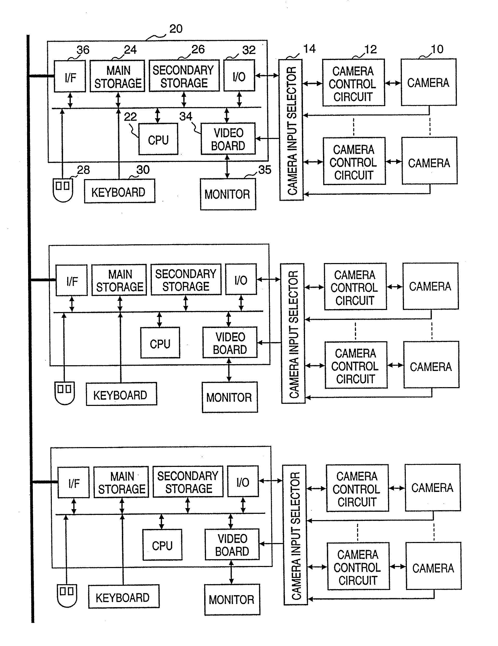
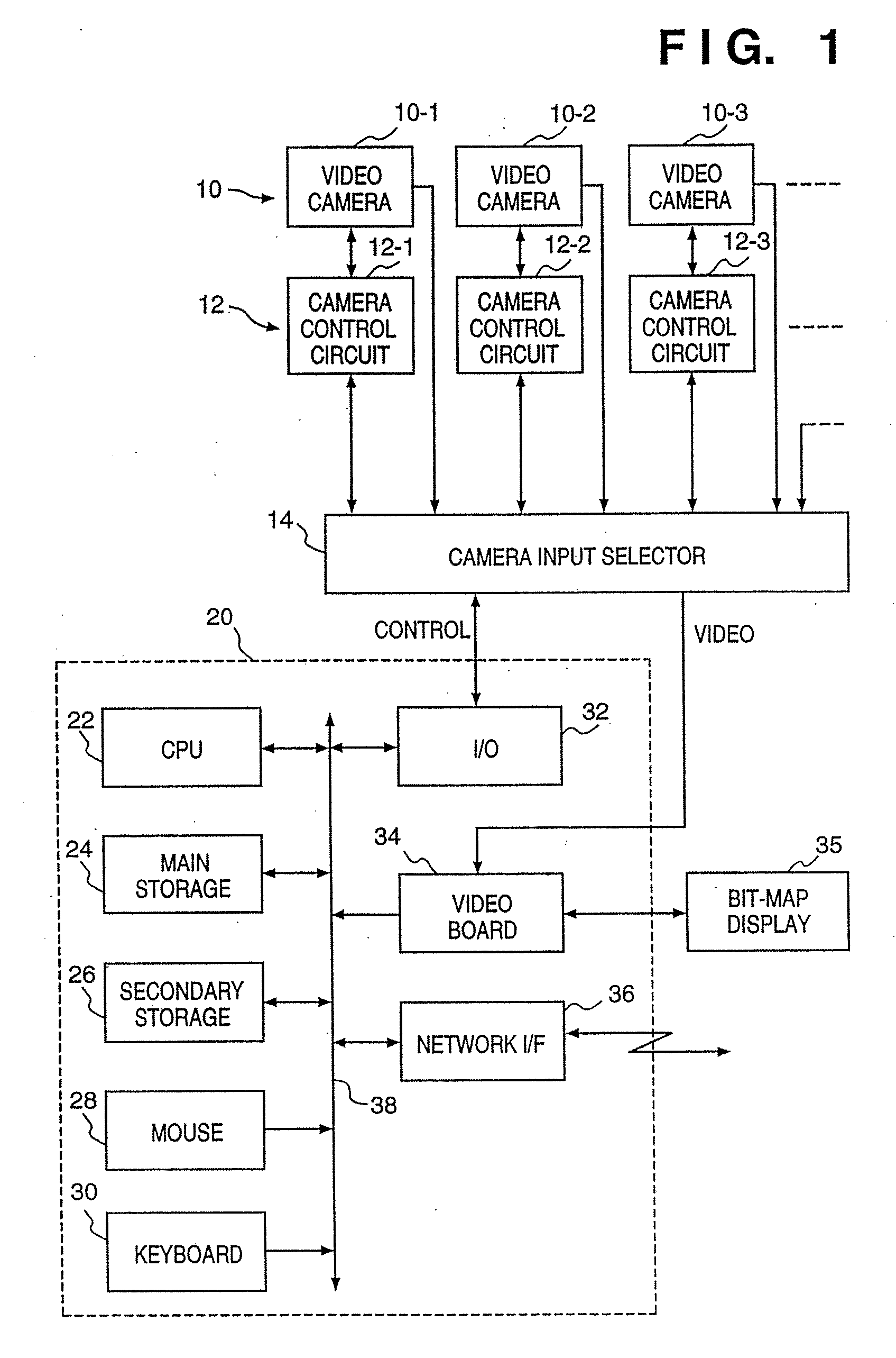
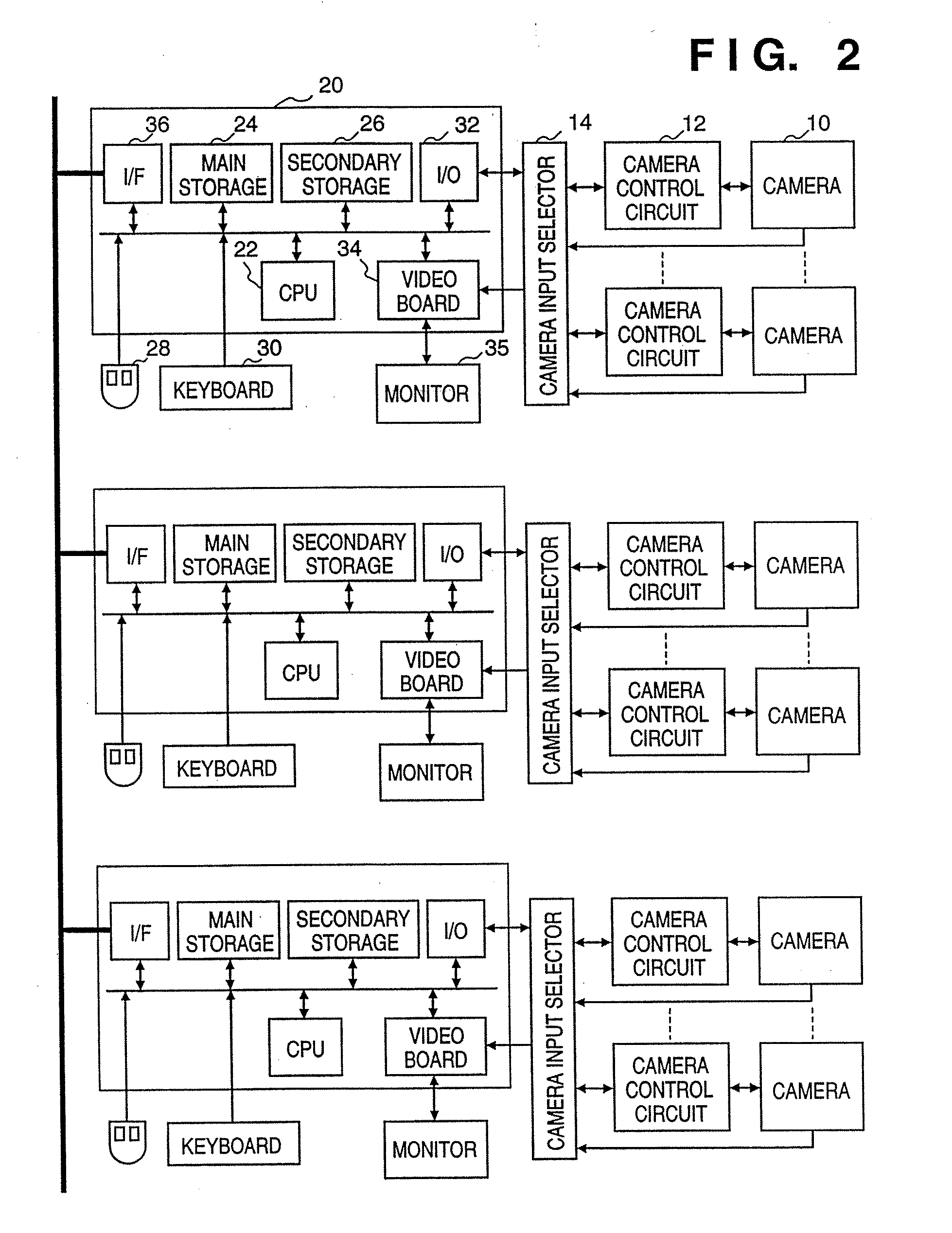
[0121]FIG. 1 is a block diagram showing an outline of the configuration of a computer system in which a plurality of video communication terminals, i.e., cameras, which are basic elements in this embodiment of the present invention, are connected. One or more computers having the configuration shown in FIG. 1 and / or one or more computers having a similar configuration are interconnected with each other via a computer network.

[0122] In FIG. 1, camera control circuits 12 (12-1, 12-2, 12-3, . . . ) directly control, e.g., panning, tilting, zooming, focus adjustment, and aperture of video cameras 10 (10-1, 10-2, 10-3, . . . ) in accordance with external control signals. A camera input selector 14 selects a video camera 10 to be controlled and inputs an output signal from the camera. RS-232C is an example of a control signal line. However, the present invention is obviously not limited to this interface. Note that although an output signal is usually a video signal, a video signal and a...

second embodiment

[0170] The second embodiment of the present invention will be described in detail below with reference to the accompanying drawings.

[0171]FIG. 19 is a block diagram showing a video communication terminal of this embodiment. A display 100 as a display unit displays a video camera control window 10, FIG. 20. A video camera 101 incorporating a zoom lens can be panned and tilted by a panhead 109 which incorporates a motor (not shown). The motion of the video camera 101 is controlled by a video camera controller 102. An image controller 103 encodes and decodes image signals. A communication controller 104 exchanges image information and video camera control information with a video camera controller installed in a remote place. A system controller 105 controls the overall system. An operation unit 106 as a designating means includes a keyboard, a mouse, and a digitizer and inputs designations to the system controller 105. These controllers constitute a control means according to this em...

third embodiment

[0189] In this embodiment, the content in step S235 of FIG. 23 in the second embodiment is changed. In the second embodiment, as described above, even if the place selected by the user is outside the video camera movable area, the user selected the place because he or she wanted to see the place. Therefore, it is desirable that the selected place be displayed even though the place is not displayed in the center of the screen. In this embodiment, this desire is positively satisfied. This embodiment will be described in detail below with reference to the accompanying drawings. Note that the system configuration is identical with that of the second embodiment shown in FIG. 19 and the GUI is also similar to that of the second embodiment shown in FIG. 20, and so detailed descriptions thereof will be omitted.

[0190]FIGS. 24A and 24B illustrate operations on a video camera control screen 112. FIG. 24A shows a normal operation in which the user selects a position inside a video camera movab...


PUM


Abstract

This invention provides an image input system capable of setting an arbitrary imaging inhibited area. This system displays a map showing the positions of cameras arranged in an office and the directions in which these cameras can be aimed, or displays the view angles of the cameras. An operator designates an imaging inhibited area on the map. In accordance with the designated imaging inhibited area, a limiting direction is calculated for each camera, and each camera is so controlled as not to point in that direction. Even when cameras are fixed, the system controls display so that an imaging inhibited area is not displayed.

Description

[0001] This application is a divisional of application Ser. No. 10 / 865,729, filed Jun. 10, 2004, which is a continuation of Ser. No. 08 / 603,611, filed Jul. 25, 2000, which is a Continued Prosecution Application of application Ser. No. 08 / 603,611 filed on Dec. 16, 1998, which is a Continued Prosecution Application of application Ser. No. 08 / 603,611 filed on Feb. 21, 1996, to which priority under 35 U.S.C. §120 is claimed and which are hereby incorporated by reference herein in their entirety as if fully set forth herein.BACKGROUND OF THE INVENTION [0002] The present invention relates to a camera control system and, more particularly, to a camera control system in which at least one operator remotely operates at least one camera. [0003] A video transmission system has been proposed in which large numbers of cameras and computers are arranged in a building and connected in a network to enable transmission of images or conversations using images and voices between two (or three or more)...

Claims


Application Information

Patent Timeline
IPC IPC(8): H04N1/46H04N5/232H04N7/18
CPCH04N5/232H04N7/181H04N23/661H04N23/631H04N23/634H04N23/695
Inventor KAWAI, TOMOAKI
Owner CANON KK
Why Eureka
Try Eureka