Method for measuring end-to-end delay in asynchronous packet transfer network, and asynchronous packet transmitter and receiver

a packet transfer network and end-to-end delay technology, applied in the field of measuring end-to-end delay in asynchronous packet transfer network, can solve the problems of difficult application to asynchronous networks such as ethernet, conventional delay measurement method, and inability to provide qos-guaranteed service implementation by existing internet structures, etc., to achieve convenient measurement of delay value and convenient

Inactive Publication Date: 2007-05-03
ELECTRONICS & TELECOMM RES INST
View PDF11 Cites 38 Cited by
  • Summary
  • Abstract
  • Description
  • Claims
  • Application Information

AI Technical Summary

Benefits of technology

[0013] The present invention is directed to conveniently and easily measuring a delay value in an asynchronous packet transfer network.

Problems solved by technology

This QoS-guaranteed service implementation cannot be provided by an existing Internet structure.
However, the conventional delay measuring method has the following problems.
Hence, it is difficult to apply to an asynchronous network such as Ethernet.
Further, when the NPT extends to the large-scaled network, a system load for NPT processing between the facilities is increased, so that the facilities can be deteriorated in performance.
In this case, support in the asynchronous network is difficult due to network synchronization.
However, since the MPLS is for uni-directional transmission and does not have the same delay in both directions, the use of the delay time is not appropriate.

Method used


Image

  • Method for measuring end-to-end delay in asynchronous packet transfer network, and asynchronous packet transmitter and receiver
  • Method for measuring end-to-end delay in asynchronous packet transfer network, and asynchronous packet transmitter and receiver
  • Method for measuring end-to-end delay in asynchronous packet transfer network, and asynchronous packet transmitter and receiver

Examples


Embodiment Construction

[0024] Hereinafter, an exemplary embodiment of the present invention will be described in detail. However, the present invention is not limited to the embodiments disclosed below, but can be implemented in various types. Therefore, the present embodiment is provided for complete disclosure of the present invention and to fully inform the scope of the present invention to those ordinarily skilled in the art.

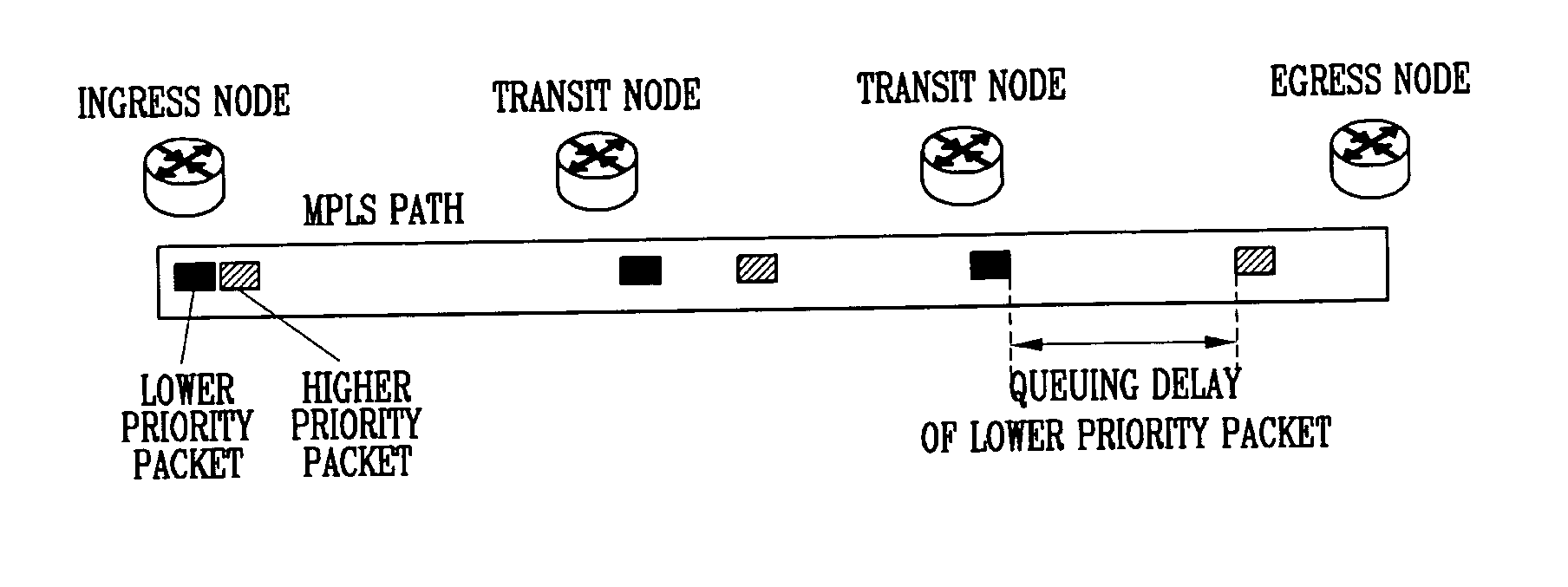
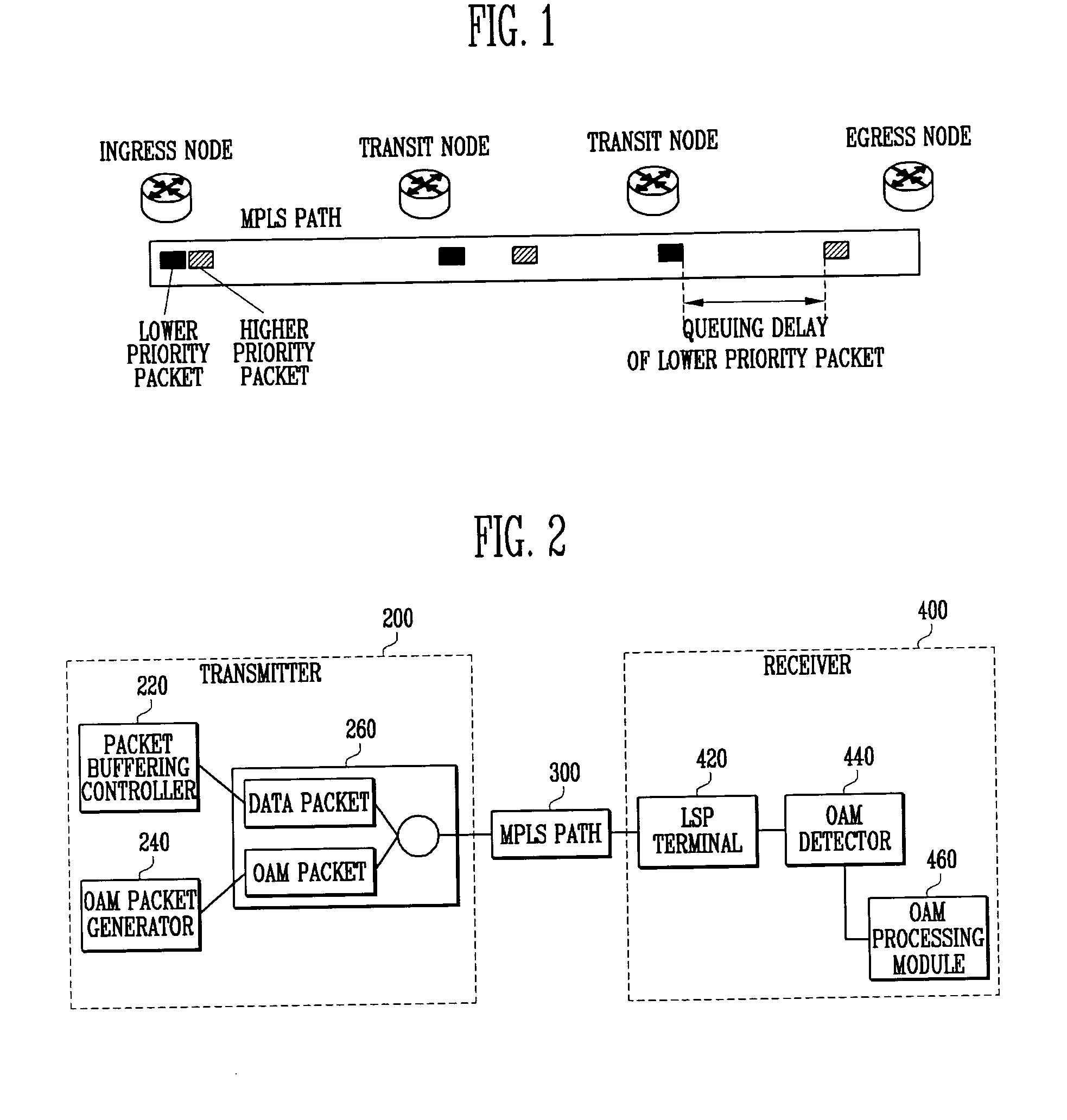
[0025] The end-to-end delay of a packet on a virtual circuit is generally divided into three types: a packet processing delay, a propagation delay, and a queuing delay caused by the buffering of a transfer node.

[0026] The packet processing delay is a delay of parsing and processing information in the header of a packet that is received from each node, and the propagation delay is a delay that constantly increases as a distance between an ingress node and an egress node is increased. Both the packet processing delay and the propagation delay account for a fixed percentage of the ...


PUM


Abstract

Provided are a method for measuring an end-to-end delay, and asynchronous packet transmitter/receiver, capable of conveniently and exactly measuring a packet delay in an asynchronous packet transfer network in which a transfer priority is determined as in MPLS. The method includes the steps of continuously transmitting a higher priority packet and a lower priority packet at an ingress node, measuring a time when the higher priority packet arrives at an egress node, measuring a time when the lower priority packet arrives at the egress node, and calculating a delay time from the arrival time of the higher and lower priority packets. The higher and lower priority packets each include Coupled Label and Sequence Number fields for discriminating one of the packets that are repeatedly transmitted, the Coupled Label field of the higher priority packet is recorded with a label value of the lower priority packet, and the Coupled Label field of the lower priority packet is recorded with a label value of the higher priority packet.

Description

CROSS-REFERENCE TO RELATED APPLICATION [0001] This application claims priority to and the benefit of Korean Patent Application No. 2005-104812, filed Nov. 3, 2005, the disclosure of which is incorporated herein by reference in its entirety. BACKGROUND [0002] 1. Field of the Invention [0003] The present invention relates to a method for effectively measuring a packet delay in an asynchronous packet transfer network. More particularly, the present invention relates to a method for measuring an end-to-end delay, and asynchronous packet transmitter and receiver, capable of conveniently and exactly measuring a packet delay in an asynchronous packet transfer network in which a transfer priority is determined as in MPLS (Multi-Protocol Label Switching). [0004] 2. Discussion of Related Art [0005] With tremendous distribution of Internet services, many users have a demand for a network structure that guarantees quality of service (QoS) and safety, as well as an end-to-end connection. This Qo...

Claims


Application Information

Patent Timeline
Patent Type & Authority Applications(United States)
IPC IPC(8): H04J1/16H04J3/14
CPCH04J3/247H04L12/2697H04L41/5022H04L43/0829H04L43/0852H04L43/0864H04L43/106H04L43/50H04L45/50H04L47/10H04L47/115H04L47/24H04L47/283H04L2012/5603
Inventor SONG, JONG TAELEE, SOON SEOK
Owner ELECTRONICS & TELECOMM RES INST
Why Eureka
Try Eureka