
System and method for measuring dispersion

a technology of optical fiber and dispersion, applied in the direction of optical elements, optical apparatus testing, instruments, etc., can solve the problems of limiting the maximum data transmission speed, the inability to measure the dispersion in the optical fiber such that it can be compensated or applied, and the inability to measure the dispersion of the group more accurately by inexpensive measuring apparatuses, etc., to achieve the effect of convenient and convenient measuremen

Inactive Publication Date: 2010-12-09
NAT CHIAO TUNG UNIV
View PDF8 Cites 3 Cited by
  • Summary
  • Abstract
  • Description
  • Claims
  • Application Information

AI Technical Summary

Benefits of technology

[0007]An object of the present invention is to provide a method for measuring dispersion in an optical fiber, so as to easily and conveniently measure the is dispersion in the optical fiber.
[0008]Another object of the present invention is to provide a measuring system, so as to utilize measuring apparatuses with low costs to measure dispersion in an optical fiber.

Problems solved by technology

Thus, for the optical fiber communication applications, the group velocity dispersion will cause neighboring signals to overlap with each other, thus limiting the maximum data transmission speed.
Therefore, how the dispersion in the optical fiber can be measured such that it can be compensated or applied is an essential issue.
However, the foregoing methods are usually restricted by response time of detectors, disturbance of circumstances, modulating frequency of modulators or measuring sensitivity, thus the group velocity dispersion cannot be measured more accurately by inexpensive measuring apparatuses.

Method used


Image

  • System and method for measuring dispersion
  • System and method for measuring dispersion
  • System and method for measuring dispersion

Examples


Embodiment Construction

[0019]In the following description, several specific details are presented to provide a thorough understanding of the embodiments of the present invention. One skilled in the relevant art will recognize, however, that the present invention can be practiced without one or more of the specific details, or in combination with or with other components, etc. In other instances, well-known implementations or operations are not shown or described in detail to avoid obscuring aspects of various embodiments of the present invention.

[0020]The terms used in this specification generally have their ordinary meanings in the art and in the specific context where each term is used. The use of examples anywhere in this specification, including examples of any terms discussed herein, is illustrative only, and in no way limits the scope and meaning of the invention or of any exemplified term. Likewise, the present invention is not limited to various embodiments given in this specification.

[0021]As use...


PUM

PropertyMeasurementUnit
dispersionaaaaaaaaaa
periodic wavelengthaaaaaaaaaa
wavelengthaaaaaaaaaa

Abstract

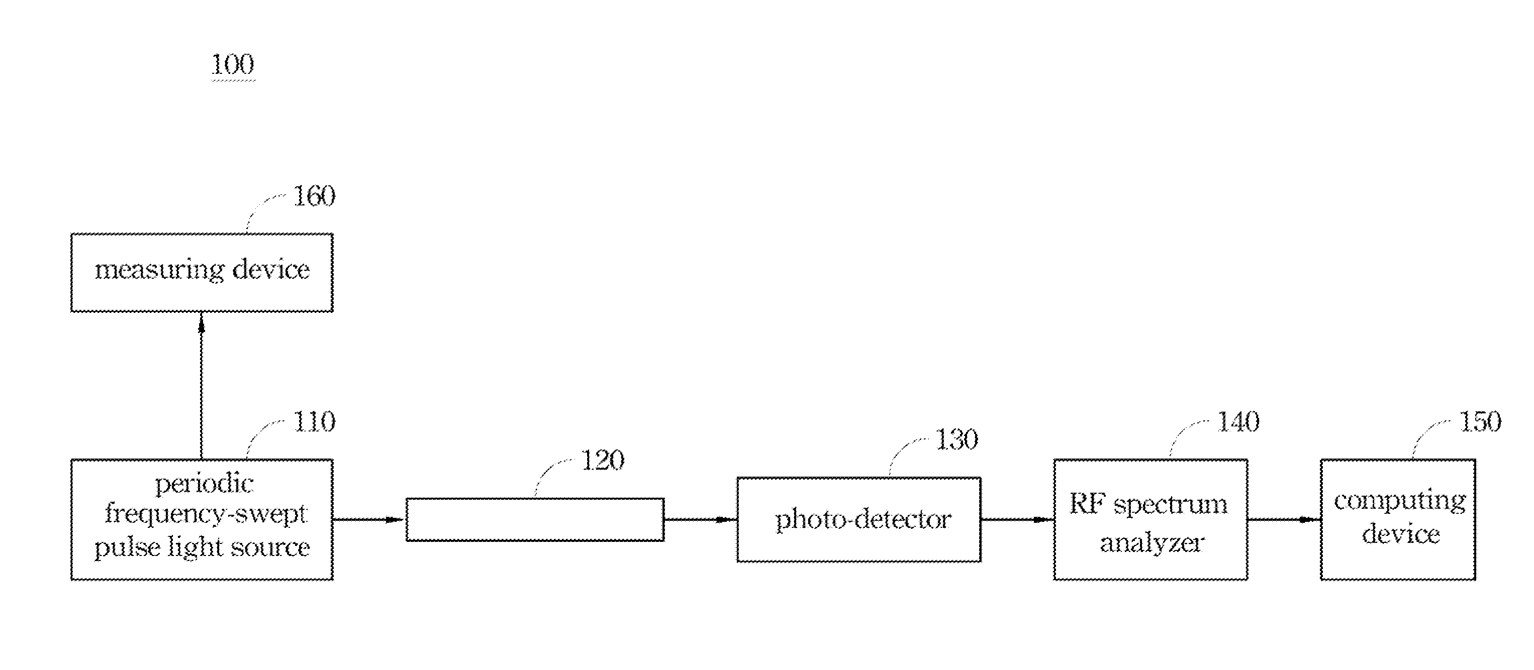
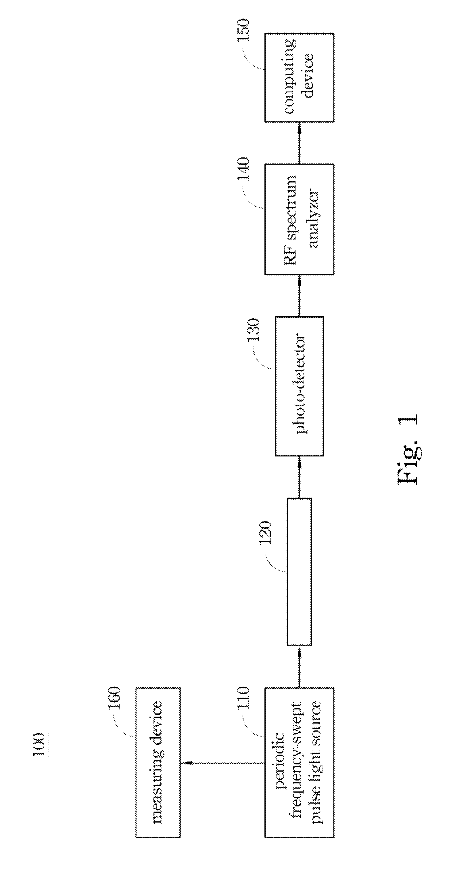
A method for measuring dispersion in an optical fiber is provided and includes the following steps. A periodic wavelength variation pulse light signal is generated by a periodic frequency-swept pulse light source, in which the periodic wavelength variation pulse light signal has periodic wavelength variations. The periodic wavelength variation pulse light signal is transmitted into a test optical fiber. The periodic wavelength variation pulse light signal propagating through the test optical fiber is detected to generate a sensing signal. The sensing signal is transformed into an RF spectrum to obtain a slow periodic pulse timing variation of the periodic wavelength variation pulse light signal in accordance with the RF spectrum. A dispersion value of the test optical fiber is obtained in accordance with the slow periodic pulse timing variation. A system for measuring dispersion in a fiber is also disclosed herein.

Description

RELATED APPLICATIONS[0001]This application claims priority to Taiwan Patent Application Serial Number 98118609, filed Jun. 4, 2009, which is herein incorporated by reference.BACKGROUND[0002]1. Technical Field[0003]The present disclosure relates to a method for measuring dispersion in an optical fiber. More particularly, the present disclosure relates to a method of using a periodic wavelength variation pulse light signal to measure dispersion in an optical fiber.[0004]2. Description of Related Art[0005]Conventionally, dispersion or group velocity dispersion (GVD) would cause a group velocity of the light to have different pulse time delays due to the light having different wavelengths when the light propagates in a transmission medium (e.g. optical fiber) having none-zero dispersion value. In other words, during the light propagation inside a dispersive fiber, the light pulse may broaden due to the fiber dispersion effect in the transmission medium. Thus, for the optical fiber commu...

Claims


Application Information

Patent Timeline
Patent Type & Authority Applications(United States)
IPC IPC(8): G01N21/00
CPCG01M11/333G01M11/335H04B10/0731G02B6/02214G01M11/338
Inventor JYU, SIAO-SHANLAI, YIN-CHIEHLIU, SHIOU-FONGHSIANG, WEI-WEICHANG, HON-CHIEH
Owner NAT CHIAO TUNG UNIV
Learn More