Hierarchical flow-level multi-channel communication

a multi-channel communication and hierarchy technology, applied in the field of communication systems, can solve problems such as capacity shortages in cable plants operating at a frequency of 750 mhz, and channel capacity shortages

Inactive Publication Date: 2007-05-03
AVAGO TECH INT SALES PTE LTD
View PDF25 Cites 97 Cited by
  • Summary
  • Abstract
  • Description
  • Claims
  • Application Information

AI Technical Summary

Benefits of technology

[0009] A communication system includes a supervisory node (e.g., a headend) and one or more remote nodes (e.g., cable modems). Packets are transmitted between the supervisory node an

Problems solved by technology

Advances in communication technology are requiring increasingly more bandwidth, which may lead to deficiencies in channel capacity, especially with respect to these downstream transmissions.
For example, even cable plants o

Method used


Image

  • Hierarchical flow-level multi-channel communication
  • Hierarchical flow-level multi-channel communication
  • Hierarchical flow-level multi-channel communication

Examples


Embodiment Construction

[0039] Although the embodiments of the invention described herein refer specifically, and by way of example, to cable modem systems, including cable modem termination systems and cable modems, it will be readily apparent to persons skilled in the relevant art(s) that the invention is equally applicable to other communication systems, including but not limited to satellite systems, optical communications systems, telephone wire systems, and / or any combination thereof. It will also be readily apparent to persons skilled in the relevant art(s) that the invention is applicable to any point-to-multipoint system.

1.0 Overview

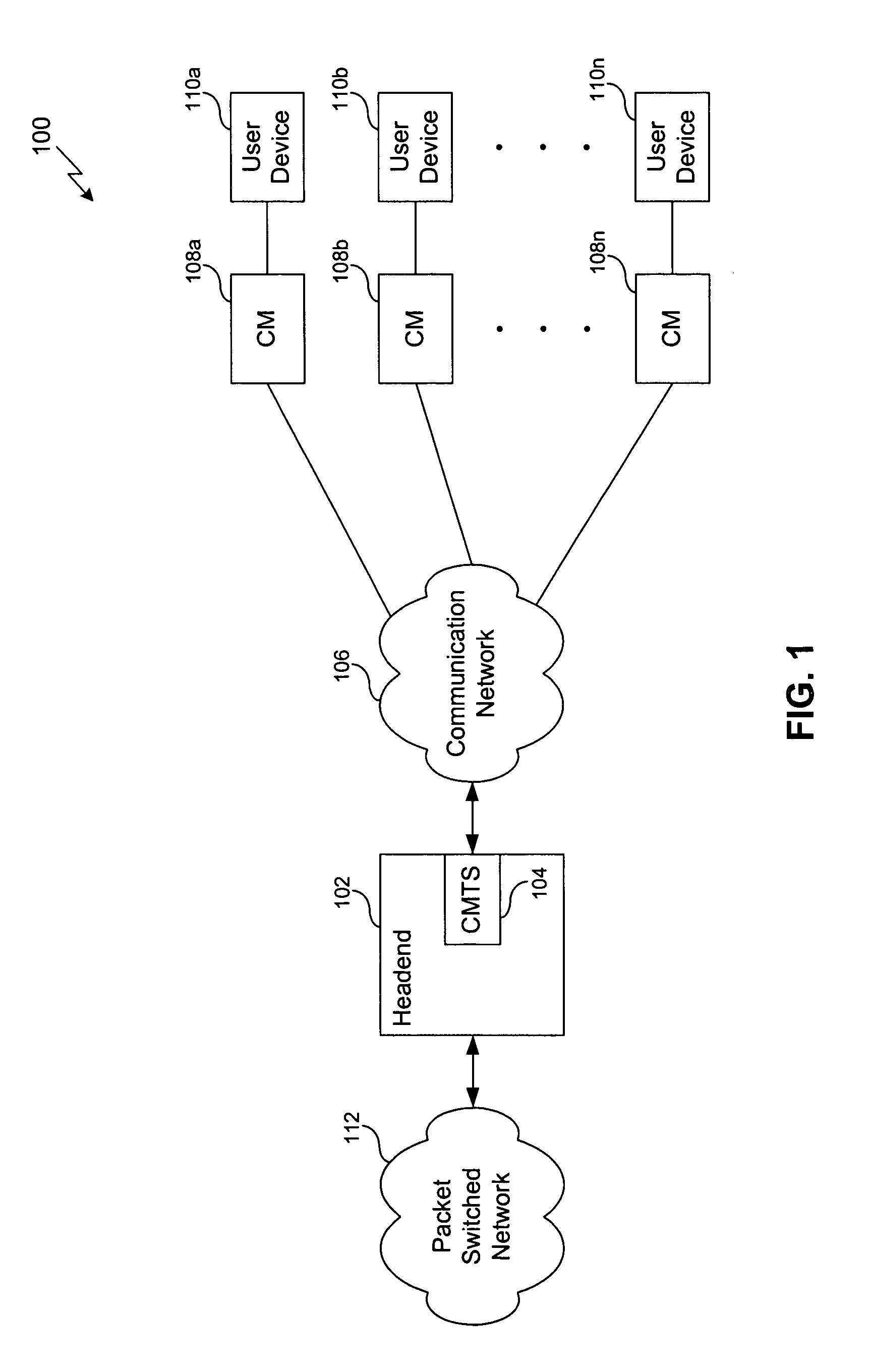
[0040]FIG. 1 illustrates a high-level block diagram of an example communication system 100 according to an embodiment of the present invention. The communication system 100 enables voice communications, audio communications, data services, video, messaging, graphics, other forms of media and / or multimedia, or any combination thereof, based on a bi-directional transf...


PUM


Abstract

A communication system that includes a supervisory node (e.g., a headend) and one or more remote nodes (e.g., cable modems). Packets are transmitted between the supervisory node and the one or more remote nodes via RF channels. A plurality of the RF channels are bonded, such that packets may be transmitted via any one or more of the RF channels that are bonded. Bonding may include higher-layer bonding and/or lower-layer bonding. In higher-layer bonding, the communication system further includes a forwarder and a plurality of edge modulators. Each edge modulator is connected to a different RF channel or group of RF channels. The forwarder determines to which edge modulator one or more packets or flows are to be transmitted. In lower-layer bonding, a packet is split into pieces. The pieces are assigned to respective RF channels that are associated with an edge modulator for transmission to a remote node.

Description

BACKGROUND OF THE INVENTION [0001] 1. Field of the Invention [0002] The present invention relates generally to communication systems, and more specifically, to managing communication over multiple channels in a communication system. [0003] 2. Related Art [0004] The present invention addresses issues relating to communication systems, and specifically point-to-multipoint communication systems. In conventional point-to-multipoint communication systems, a network supports bidirectional data communication between a central entity and multiple customer premises equipment (CPE). Example point-to-multipoint communication systems include cable modem systems, fixed wireless systems, and satellite communication systems. In each system, the communication path from the central entity to the CPE is typically referred to as the downstream, while the communication path from the CPE to the central entity is typically referred to as the upstream. [0005] One type of point-to-multipoint system is a ca...

Claims


Application Information

Patent Timeline
IPC IPC(8): H04B7/212H04N7/16H04L45/24H04N7/173
CPCH04L12/2801H04N7/16H04N7/17309H04N21/2385H04N21/6118H04N21/6168H04L45/24H04N21/658H04L5/0007H04L25/14H04L27/34H04L69/14Y02B60/33H04N21/6377Y02D30/50
Inventor PRODAN, RICHARD S.DANZIG, JOELQUIGLEY, THOMAS J.PANTELIAS, NIKI R.
Owner AVAGO TECH INT SALES PTE LTD
Why Eureka
Try Eureka