Detection of large carrier offsets using a timing loop

a timing loop and carrier offset technology, applied in the field of carrier recovery, can solve the problems of timing recovery process, receiver data may be corrupted, timing recovery process not always independent,

Active Publication Date: 2007-05-03
AVAGO TECH INT SALES PTE LTD
View PDF1 Cites 59 Cited by
  • Summary
  • Abstract
  • Description
  • Claims
  • Application Information

AI Technical Summary

Problems solved by technology

Unfortunately, the timing recovery process and the carrier recovery process are not always independent.
In fact, a large carrier offset may prohibit the timing recovery process from obtaining symbol synchronization.
As a result, the data of the receiver may be corrupt.
Blindly stepping through carrier offsets and determ

Method used


Image

  • Detection of large carrier offsets using a timing loop
  • Detection of large carrier offsets using a timing loop
  • Detection of large carrier offsets using a timing loop

Examples


Embodiment Construction

[0017] The following detailed description of the present invention refers to the accompanying drawings that illustrate exemplary embodiments consistent with this invention. Other embodiments are possible, and modifications may be made to the embodiments within the spirit and scope of the invention. Therefore, the detailed description is not meant to limit the invention. Rather, the scope of the invention is defined by the appended claims.

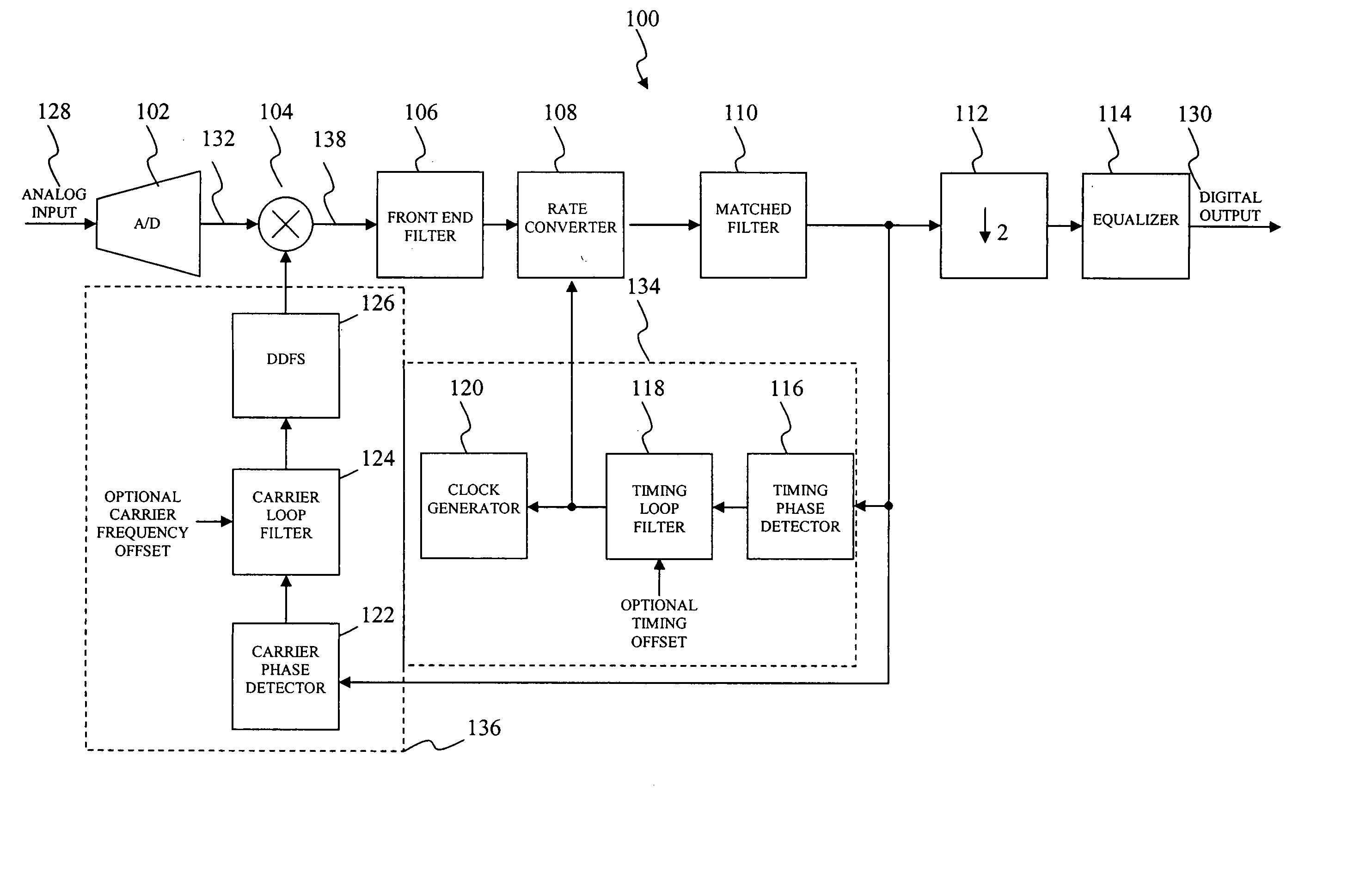
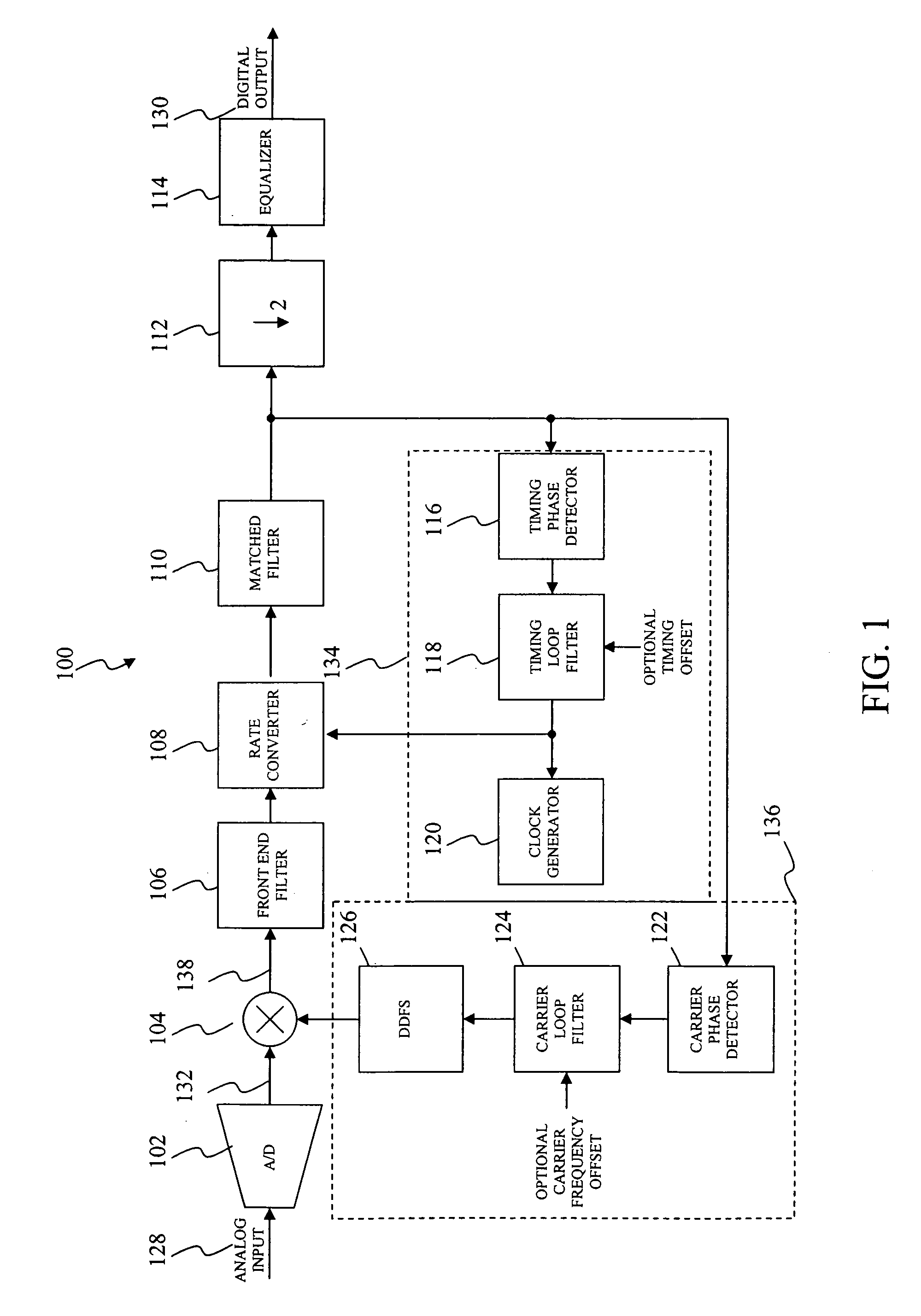
[0018]FIG. 1 is an illustration of a block diagram of a digital receiver system according to an embodiment of the present invention. Digital receiver system 100 uses a timing recovery loop that cannot operate in the presence of a large carrier offset. Accordingly, the present invention is generally applicable to any digital receiver system that uses a digital PLL for timing recovery whose performance degrades in the presence of a large carrier offset. For example, the present invention is applicable to the commonly used Gardner timing loop.

[0019] ...


PUM


Abstract

A method and apparatus for the detection and correction of large carrier offsets. A set of known correction carrier offsets are used to translate an input signal having a carrier offset. After applying each correction carrier offset, a state of a timing recovery loop is evaluated. The set of known correction carrier offsets are sequentially used to translate the input signal until the timing recovery loop is locked. The carrier offset is substantially acquired when the timing recovery loop is locked.

Description

CROSS-REFERENCE TO RELATED APPLICATIONS [0001] This patent application claims the benefit of U.S. Provisional Patent Application No. 60 / 730,359, filed Oct. 27, 2005, entitled “Detection of Large Carrier Offsets Using a Timing Loop,” which is incorporated herein by reference in its entirety.BACKGROUND OF THE INVENTION [0002] 1. Field of the Invention [0003] The present invention generally relates to carrier recovery. More specifically, the present invention relates to the recovery of carrier offsets using a timing recovery loop. [0004] 2. Background Art [0005] Communication systems allow for communication over large distances by using sophisticated transponders in a satellite. Transponders may sometimes operate on an interplanetary scale. Transponders receive incoming communications over a band of frequencies, the uplink, and retransmit the communications over another band of frequencies, the downlink, at the same time. For example, transponders most frequently use the C band with an...

Claims


Application Information

Patent Timeline
IPC IPC(8): H04L27/00H03D3/24H04L27/06
CPCH03J7/02H03J2200/02H04L27/0014H04L2027/0034H04L2027/0055H04L2027/0073
Inventor HUNDHAUSEN, AMY GAYLEYU, TOMMY
Owner AVAGO TECH INT SALES PTE LTD
Why Eureka
Try Eureka