Putter head

Inactive Publication Date: 2007-05-03
BRIDGESTONE SPORTS
View PDF34 Cites 6 Cited by
  • Summary
  • Abstract
  • Description
  • Claims
  • Application Information

AI Technical Summary

Benefits of technology

[0018] In the aspect, particularly preferably, the projecting portion is formed on the central portion of the inner surface of the high-hardness portion and both lateral peripheral portions, and a proportion of a total planar area of the projecting portion to a planar area of the inner surface of the high-hardness portion in the central portion is set to be greater than a proportion of a total planar area of the projecting portion to the planar area of the inner surface of the high-hardness portion in the peripheral portions. Namely, in the putting, if the golf ball is hit by a peripheral portion of the face surface, the putter head vibrates greatly, and it is normally impossible to obtain a satisfactory hitting sensation. In contrast, when the total planar area of the projecting portion(s) is dense in

Problems solved by technology

However, with the conventional putter head with the face insert fitted in the head body, while the hitting sensation can be made soft by the f

Method used


Image

  • Putter head
  • Putter head
  • Putter head

Examples


first embodiment

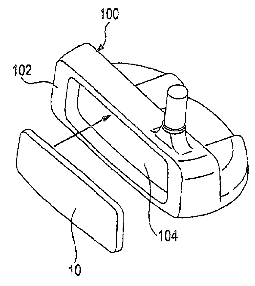
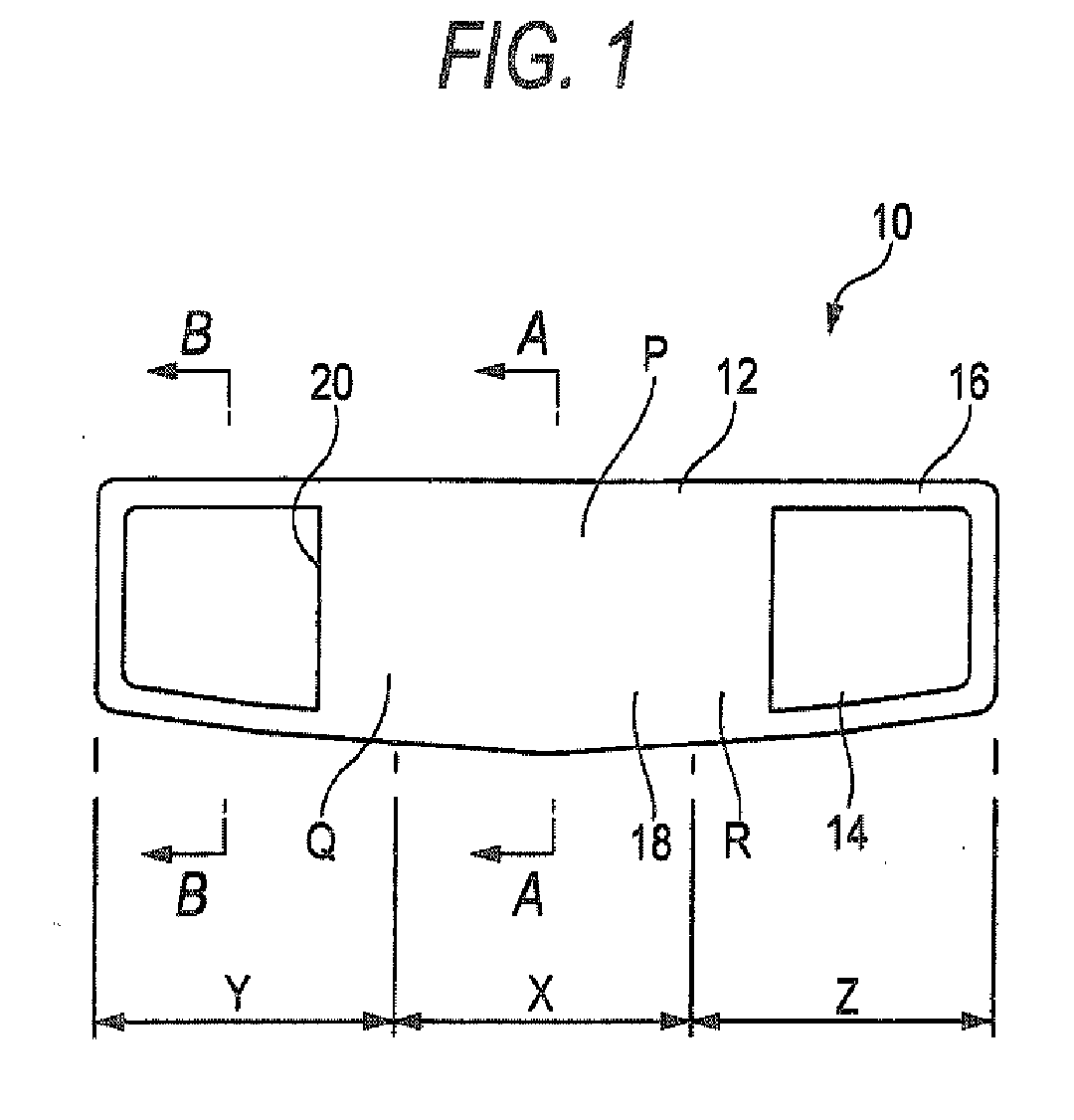
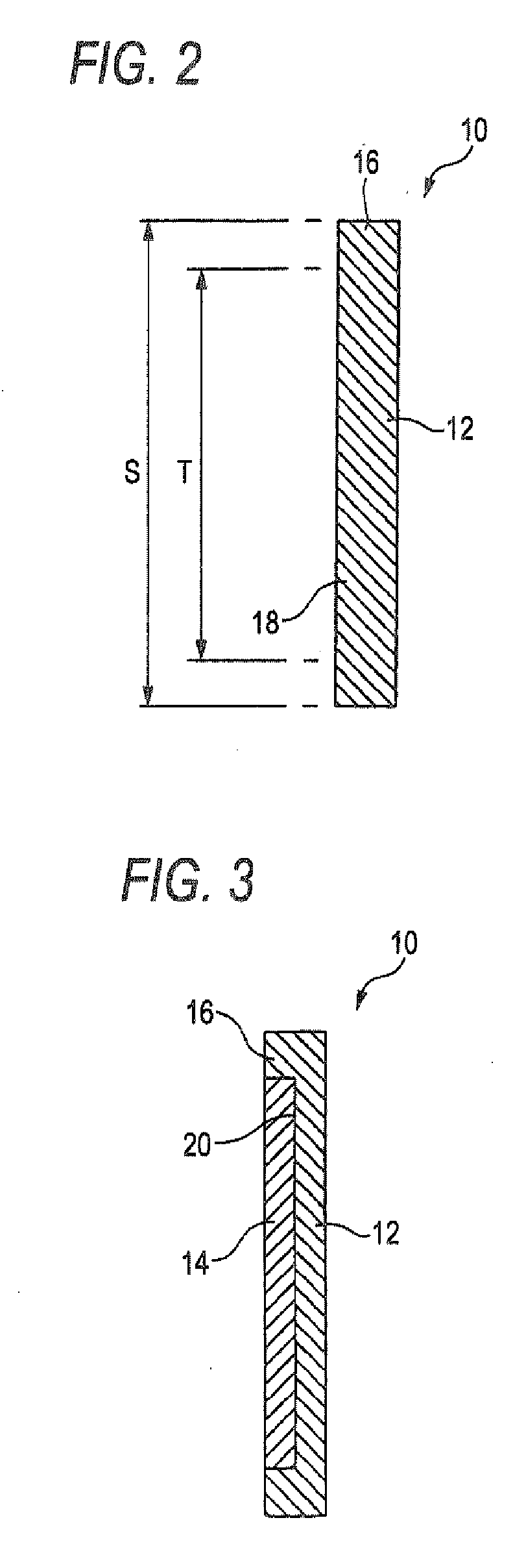
[0031]FIG. 1 is a rear view illustrating a face insert used in a putter head according to a first embodiment the invention. FIG. 2 is a cross-sectional view taken along line A-A in FIG. 1. FIG. 3 is a cross-sectional view taken along line B-B in FIG. 1. A face insert 10 in accordance with this embodiment includes a high-hardness portion 12 forming a hitting surface and a pair of low-hardness portions 14 whose hardness is lower than that of the high-hardness portion 12. The face insert 10 of this embodiment includes the high-hardness portion 12 that is formed in a plate-shape. A frame-like body 16 is provided projectingly along peripheral edges of the plate-shaped high-hardness portion 12. The high-hardness portion 12 includes a projecting portion 18 having a substantially rectangular shape. The projecting portion 18 is provided such that it extends from a central portion toward its both lateral peripheral portions. The frame-like body 16 and the projecting portion 18 are formed inte...

second embodiment

[0032]FIG. 5 is a rear view illustrating a face insert used in a putter head according to a second embodiment of the invention. FIG. 6 is a cross-sectional view taken along line A-A in FIG. 5. A face insert 30 in accordance with this embodiment includes a high-hardness portion 32 for forming the hitting surface and a low-hardness portion 34 whose hardness is lower than that of the high-hardness portion 32. In addition, in the face insert 30 of this embodiment, a frame-like body 36 is provided projectingly along peripheral edges of the plate-shaped high-hardness portion 32. Plural cylindrical projecting portions 38 are formed on the inner side of the frame-like body 36. The low-hardness portion 34 is joined to the high-hardness portion 32 so as to fill a recessed portion 40 formed by the frame-like body 36 and the projecting portions 38. In the face insert 30 of this embodiment, the proportion of a total planar area (G×9) of the projecting portions 38 to the planar area of the high-h...

third embodiment

[0033]FIG. 7 is a rear view illustrating a face insert used in a putter head according to a third embodiment of the invention. FIG. 8 is a cross-sectional view taken along line A-A in FIG. 7. A face insert 50 in accordance with this embodiment is almost the same as the second embodiment except that the frame-like body is not provided projectingly on the peripheral edges of the plate-like high-hardness portion 32. In FIGS. 7 and 8, the same component portions as those shown in FIGS. 5 and 6 are denoted by the same reference numerals, and a description thereof is omitted herein.


PUM


Abstract

A putter head that includes: a head body having a face portion; and a face insert fitted in the face portion, the face insert including a high-hardness portion that forms a hitting surface, a low-hardness portion jointed to the high-hardness portion and having a hardness lower than that of the high-hardness portion, and a projecting portion formed at least on a central portion of the high-hardness portion, the low-hardness portion filling a recessed portion formed by the projecting portion.

Description

BACKGROUND OF THE INVENTION [0001] 1. Field of the Invention [0002] The present invention relates to a putter head with a face insert fitted in a face portion of a head body. [0003] 2. Description of the Related Art [0004] Conventionally, a putter head has been proposed in which a face insert made of a material different from that of a head body is fitted in a face portion of the head body. For example, JP-A-2004-236985 discloses a putter head in which a face insert having a layered structure integrally including a rubber elastic body layer, a sintered metal layer, and a fluororesin layer is fitted in the face portion of the head body. In addition, JP-A-2005-124730 discloses a putter head in which an elastic body-made face insert whose thickness increases gradually from the side of the vicinity of a sweet spot of the head toward a peripheral edge side is fitted in a face portion of a head body. SUMMARY OF THE INVENTION [0005] The above-described putter head with the face insert fitt...

Claims


Application Information

Patent Timeline
IPC IPC(8): A63B53/00A63B53/04A63B102/32
CPCA63B53/0487A63B2053/0425A63B2053/0458A63B2053/0416A63B53/0416A63B53/0425A63B53/0458
Inventor TATENO, ATSUO
Owner BRIDGESTONE SPORTS
Why Eureka
Try Eureka