I-Beam Trolley

Inactive Publication Date: 2007-05-10
BRITCHER JAMES K
View PDF10 Cites 6 Cited by
  • Summary
  • Abstract
  • Description
  • Claims
  • Application Information

AI Technical Summary

Benefits of technology

[0017] Accordingly, such a rail/I-beam, trolley and brake system provides for the secure gripping of the bag to the an I-beam when the brake is locked

Problems solved by technology

It has been discovered by the inventor that the state of the art such trolley and their brake and release mechanism are not suitable to support kick/punching bags that are used in a gymnasium or dojo.
However, such deployment must be do

Method used


Image

  • I-Beam Trolley
  • I-Beam Trolley
  • I-Beam Trolley

Examples


Example

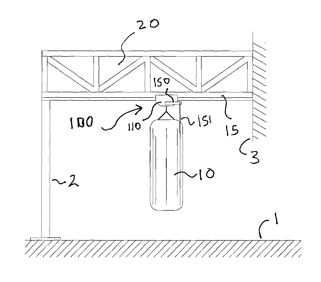
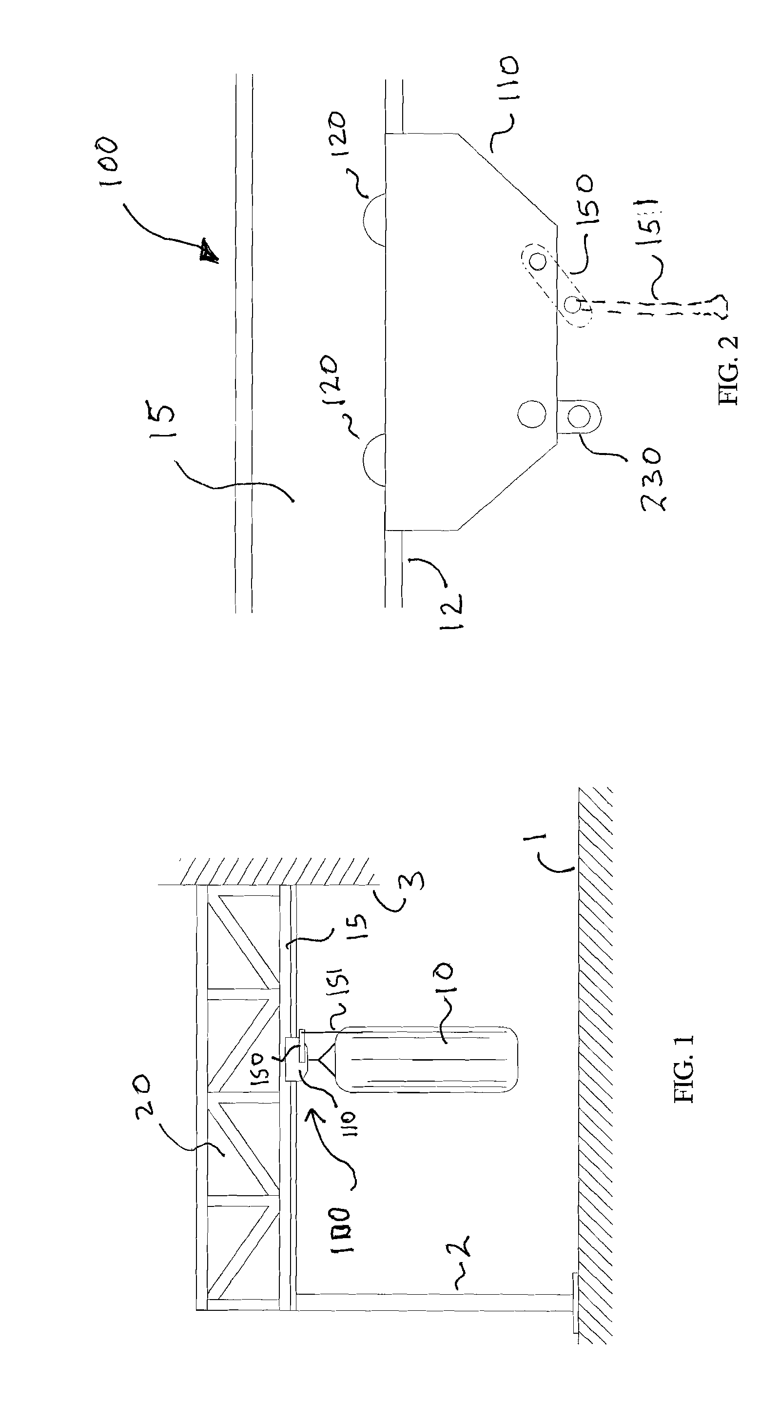
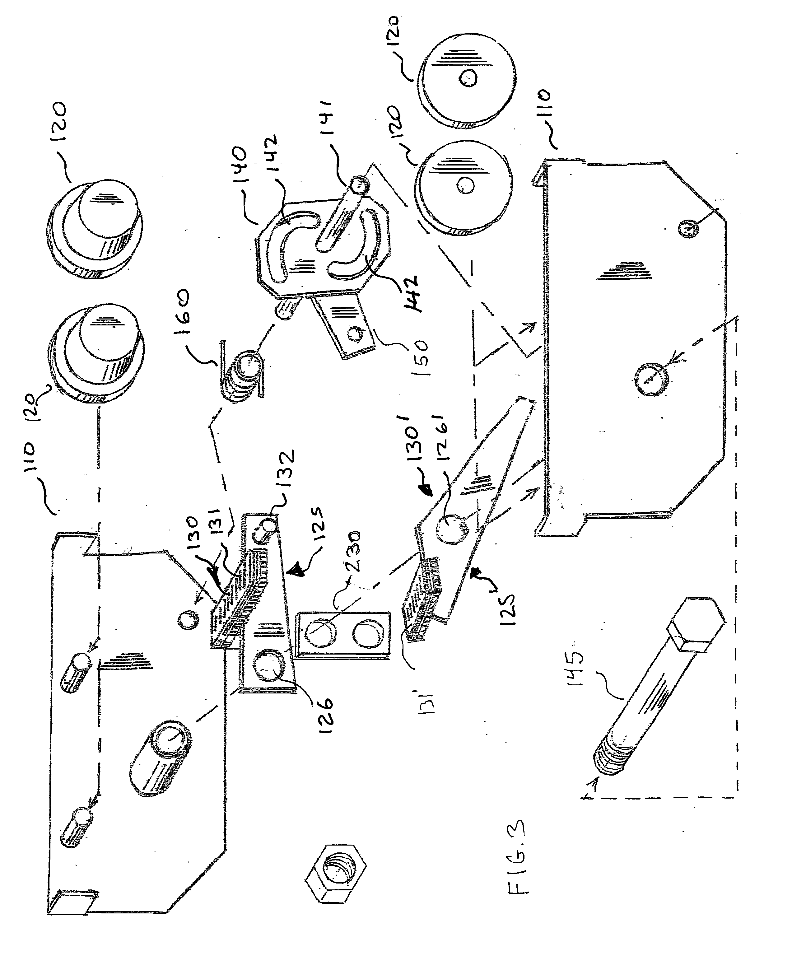
[0028] Referring to FIGS. 1 through 5, wherein like reference numerals refer to like components in the various views, there is illustrated therein a new and improved I-Beam Trolley, generally denominated 100 herein.

[0029] In accordance with the present invention, the kick bag 10 is suspended from the I-beam trolley 100. The trolley rollingly engages I-beam 15. I-beam 15 is suspended above the floor 1 at a first position by a post 2. The other side of the I-beam 15 is shown as being held by a vertical surface 3 which is optionally another post, a wall or a overhead descending fixture or support. The I-beam is stiffened by an integral truss 20.

[0030] The I-beam trolley in FIG. 1 through 4 comprises a trolley body made of plates 110, having wheels 120 that engage the horizontal extending track or ledge 11 of I-beam 15. When the bag 10 has been moved to the desired location, and is not intended to move when kicked, the trolley 100 is prevented from rolling via wheel 120 by a braking m...


PUM


Abstract

A trolley for transporting objects hanging from an I-beam normally securely grips or latches to the I-beam via a pair of brake pads that are urged upward against the bottom of the beam by a torsion spring. The torsion spring is released by pulling a lever downward. Applying lateral force to the trolley, preferably by applying a lateral force to the same lever, pulls the trolley along the I-beam as the wheels engaging the upper portion of the I-beam can rotate freely once the brake pads are released. Releasing the lever after the trolling is pulled to the desired location causes the brakes to again firmly grip the I-beam.

Description

CROSS REFERENCE TO RELATED APPLICATIONS [0001] The present application claims priority to the U.S. provisional application having Ser. No. 60 / 736,518 entitled “Trolley Brake”, filed on Nov. 10, 2005 by the Applicant, James K. Britcher, which is incorporated herein by reference. [0002] The present application also claims priority to the U.S. provisional application having Ser. No. 60 / 754,588 entitled “Kick Bag Trolley Beam System”, filed on Dec. 19, 2005 by the Applicant, James K. Britcher, which is incorporated herein by reference.BACKGROUND OF INVENTION [0003] The present invention relates to a system and apparatus for transporting objects along an overhead beam or track, and in particular to a transport mechanism having a braking means particular suitable for the transport of punching or kick bags in a gymnasium or Dojo. [0004] Prior methods of using an overhead transport system are well known. [0005] Typically, a rolling trolley is suspended from an overhead rail or track. The tr...

Claims


Application Information

Patent Timeline
IPC IPC(8): B61B3/00
CPCA63B69/201B61B3/00B65G9/006A63B69/305
Inventor BRITCHER, JAMESK
Owner BRITCHER JAMES K
Why Eureka
Try Eureka