[0015] To overcome the problems described above, preferred embodiments of the present invention provide a further miniaturized balanced acoustic wave filter having efficiently improved out-of-band attenuation, thus, having a favorable filter characteristic, and also provide an acoustic wave filter device including the acoustic wave filter.
[0028] On the other hand, according to preferred embodiments of the present invention, common connection of the common midpoint grounded portion is achieved on the acoustic wave substrate. Thus, an electrical midpoint exists on the acoustic wave substrate, the distance between the common midpoint grounded portion and the electrical midpoint is reduced, the impedance between them is reduced, balance is improved, and out-of-band attenuation of the filter is improved. That is, the attenuation on a high-frequency side of a pass band is improved by connecting the separated common midpoint grounded portion and the unbalanced-side grounded portion by impedance or
inductance. The
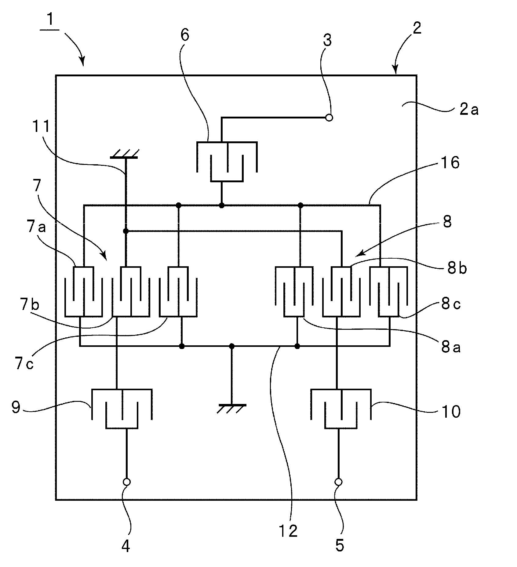
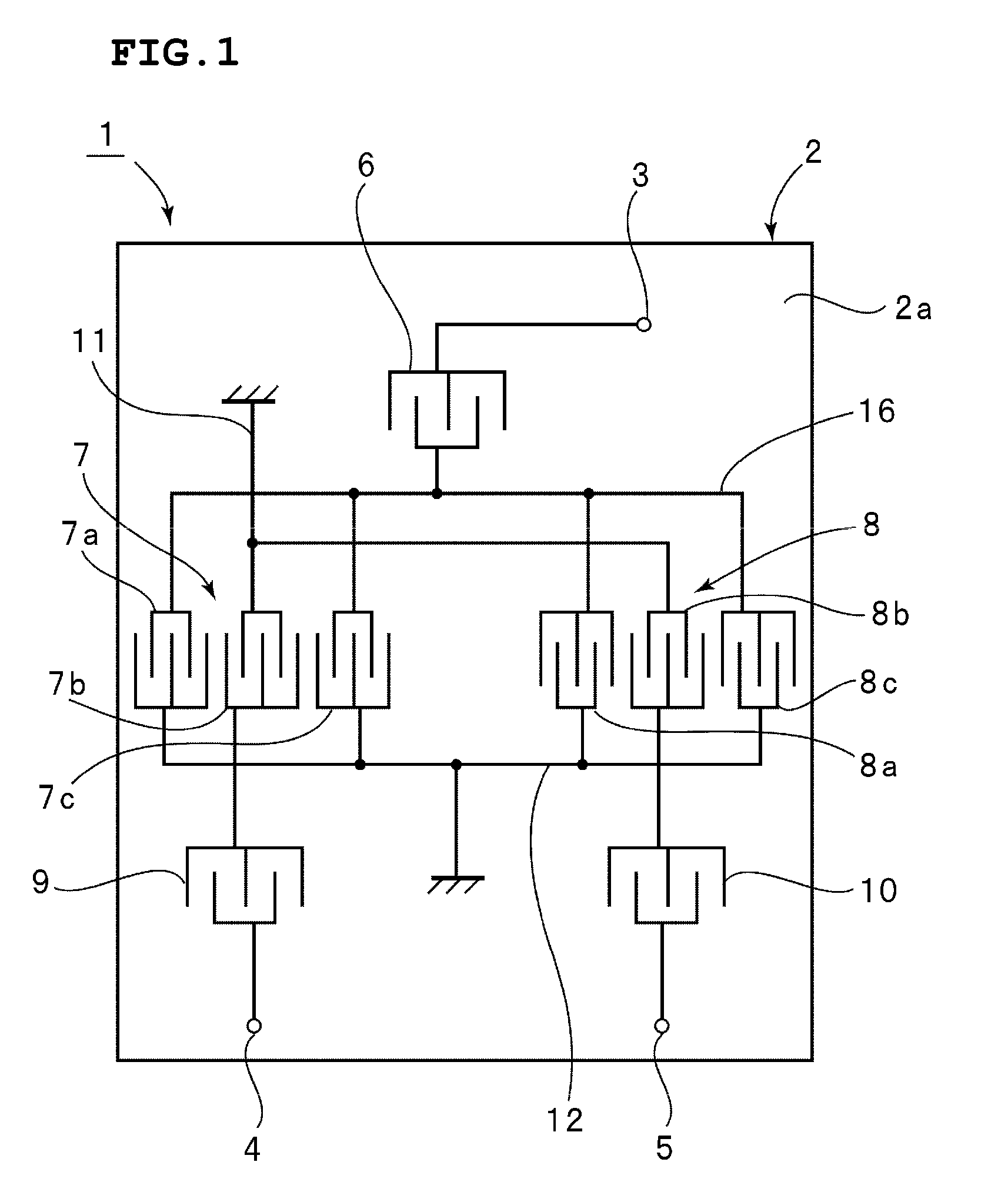
inductance value in this case is not limited, but may be about 0.1 nH to about 10 nH. In addition, on the acoustic wave substrate, the grounded ends of the IDTs of the first
filter element connected to the unbalanced terminal and the grounded ends of the IDTs of the second
filter element connected to the unbalanced terminal are mutually connected by the second connecting line so that the unbalanced-side grounded portion is provided. That is, the ground on the unbalanced side is shared on the acoustic wave substrate. Accordingly, flow of
ground current can be appropriately controlled, whereby out-of-band attenuation is expanded.
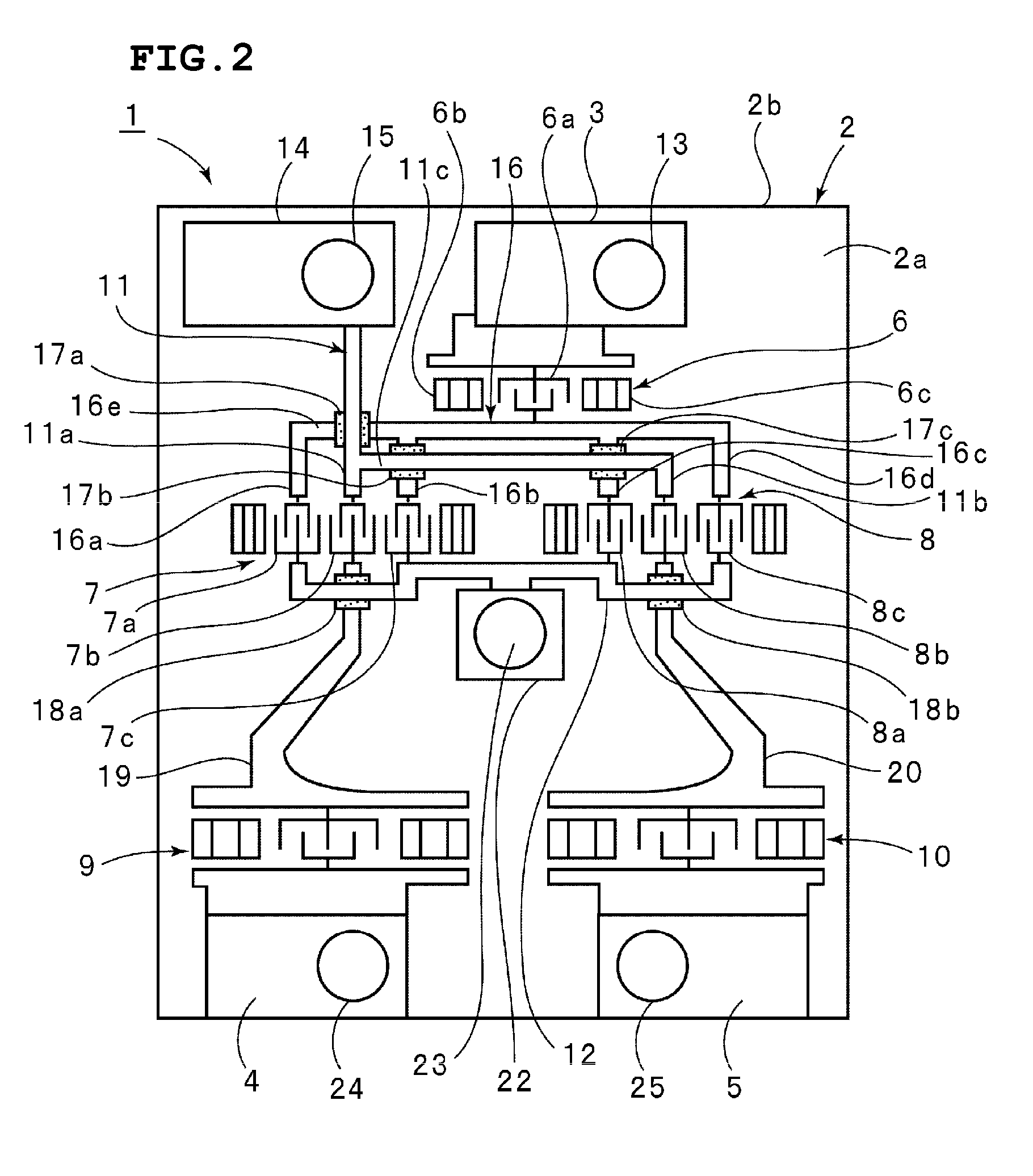
[0030] In preferred embodiments of the present invention, the third connecting line connecting at least one of the IDTs connected to the unbalanced terminal to the unbalanced terminal crosses the first connecting line on the acoustic wave substrate. At the intersections therebetween, interlayer insulating films are disposed between the first and third connecting lines. In that case, the interlayer insulating films reliably prevent short-circuits between the first and third connecting lines. Also, since the first and third connecting lines cross each other, the length of the first and third connecting lines is shortened, and connecting lines and electrodes are provided at
high density on the acoustic wave substrate. Accordingly, the acoustic wave filter is further miniaturized.
[0033] In the acoustic wave filter device, the first and second balanced acoustic wave filters as the balanced acoustic wave filters according to preferred embodiments the present are provided on the acoustic wave substrate, the
center frequency of the first balanced acoustic wave filter is different from the
center frequency of the second balanced acoustic wave filter, the common midpoint grounded portions of both of the filters are mutually connected, and the unbalanced-side grounded portions of the both filters are mutually connected. Furthermore, the acoustic wave filter device includes the
package including the first to third
electrode lands, the common midpoint grounded portion is connected to the first
electrode land by a bump, the unbalanced-side grounded portion of the first balanced acoustic wave filter is connected to the second
electrode land by a bump, the unbalanced-side grounded portion of the second balanced acoustic wave filter is connected to the third electrode land by a bump, and the first to third electrode lands are separated from each other. In this case, a plurality of acoustic wave filters having a balance-unbalance converting function can be configured into a
chip component including an acoustic wave substrate. Furthermore, a miniaturized acoustic wave filter device in which the acoustic wave filter
chip is connected to the
package substrate by bumps is provided. In this acoustic wave filter device, the first to third electrode lands are separated from each other on the package, so that isolation between the first and second balanced acoustic wave filters is improved.

