Built-in antenna having center feeding structure for wireless terminal

a wireless communication terminal and built-in antenna technology, applied in the structural form of resonant antennas, elongated active elements, radiating elements, etc., can solve the problem of serious degradation of antenna characteristics

Inactive Publication Date: 2007-05-10
ACE TECH
View PDF12 Cites 19 Cited by
  • Summary
  • Abstract
  • Description
  • Claims
  • Application Information

AI Technical Summary

Benefits of technology

[0012] It is, therefore, an object of the present invention to provide a built-in antenna that can be mounted on a terminal with a small antenna contact surface by positioning a feed point supplying electromagnetic signals in the center of the antenna to thereby have a non-directional radiation pattern.

Problems solved by technology

Moreover, since the size of the contact surface with the antenna is changed according to whether the folder cover of the terminal is open or closed, the antenna characteristics are degraded seriously.

Method used


Image

  • Built-in antenna having center feeding structure for wireless terminal
  • Built-in antenna having center feeding structure for wireless terminal
  • Built-in antenna having center feeding structure for wireless terminal

Examples


first embodiment

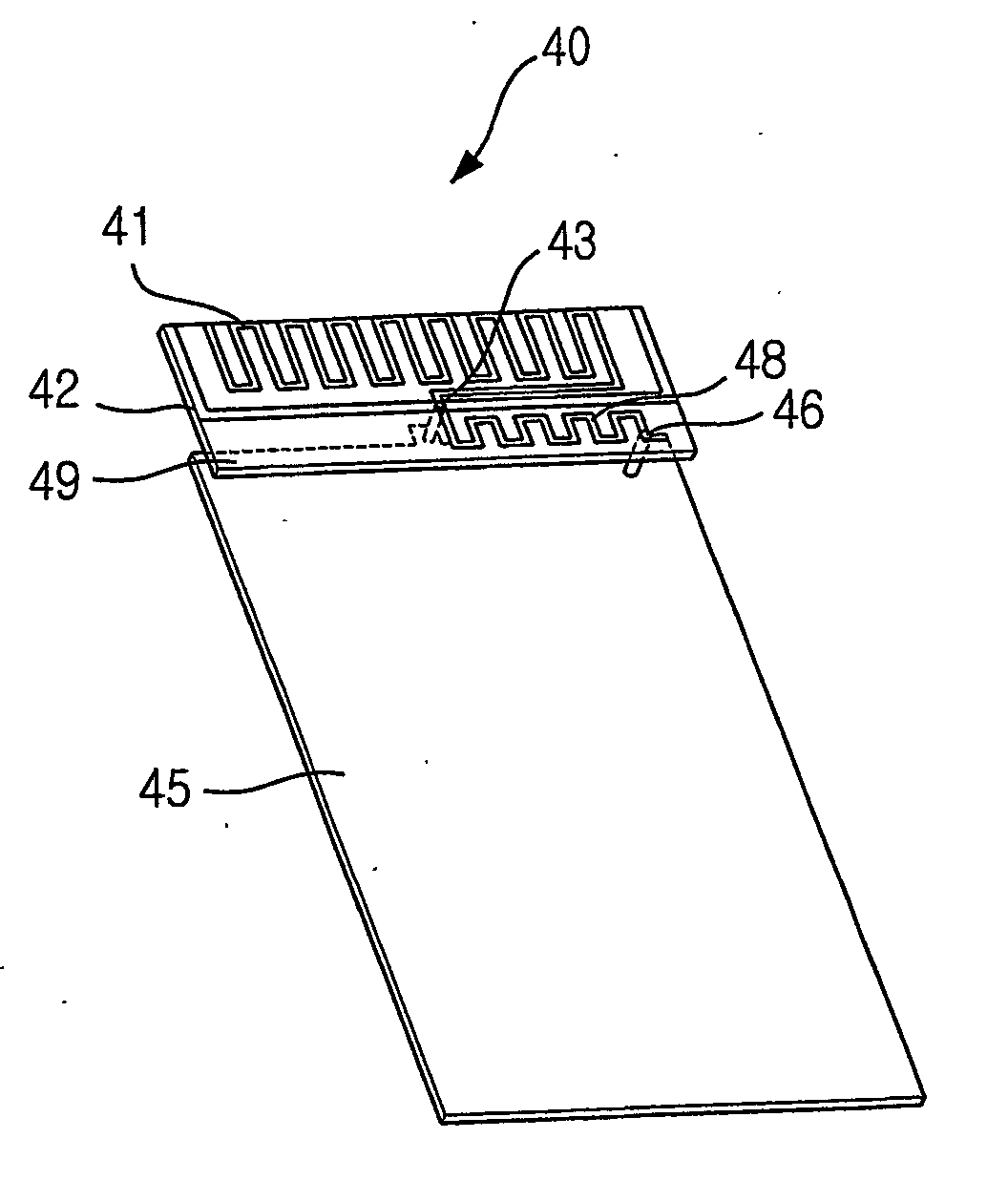
[0032]FIG. 4 is a plane view showing a built-in antenna 40 in accordance with the present invention.

[0033] As shown, the built-in antenna 40 of the present invention includes a feed point 43, a first radiator 41, and a second radiator 42. The feed point 43 supplies electromagnetic signals, and the first radiator 41 releases the GSM band electric waves with respect to the supplied electromagnetic signals. The second radiator 42 releases the DCS band electric waves.

[0034] As shown in FIG. 4, it is desirable to minimize offset current and cause constructive interference by making the first radiator 41 and the second radiator 42 release the electromagnetic signals in the same direction.

[0035] Also, the second radiator 42 has branches stretched out in both right and left directions with the feed point at the center so that the electromagnetic signals of the DCS band are distributed to the entire contact surface 45 of the terminal and thus non-directional waves are released.

[0036] The ...

fifth embodiment

[0056]FIG. 9 is a side view showing a built-in antenna in accordance with the present invention. Therefore, the antenna 90 positioned in the upper part of a contact surface 95 includes a first radiator 91, a second radiator 92, a feed point 93, and a short circuit pin 96. The first radiator 91 releases GSM-band electric waves and the second radiator 92 releases DCS-band electric waves. The feed point 93 supplies electromagnetic signals to the antenna 90, and the short circuit pin 96 shorts the antenna 90 to the contact surface 95 of the terminal.

[0057] In this embodiment of the present invention, the hand effect, which means loss by the contact to a human body, can be reduced by making an outward turn on the entire or part of the first radiator 91 that is positioned in the upper part of the antenna 90. As shown in FIG. 9, since the first radiator 91 is turned outward from the antenna 90, it can be far from the human body using the terminal, thus reducing the hand effect.

[0058] In F...


PUM


Abstract

A built-in antenna having a center feed structure for wireless terminal. The antenna includes: a feeding means for providing an electromagnetic signal; and a radiating means for radiating the electromagnetic signal, wherein the feeding means is located on a point ranging from a midpoint of the antenna. The antenna radiates a nondirectional signal and can be embedded in a wireless terminal.

Description

TECHNICAL FIELD [0001] The present invention relates to a built-in antenna for a wireless communication terminal which has a central feed structure. BACKGROUND ART [0002] As a part of a trend for miniaturizing wireless communication terminal, there is an attempt to set up an antenna inside a wireless communication terminal. [0003]FIG. 1 shows a structure of a conventional built-in antenna having a meander line structure. As shown in the drawing, the conventional built-in antenna 10 includes a radiator 12 for radiating the Global Standard for Mobile Communication (GSM) band, which is 900 MHz, to use multi-bands; a radiator 14 for radiating the Digital Command Signal band (DCS), which is 1800 MHz; and a feed point 16 for supplying electromagnetic signals to the antenna in the upper-left part of the antenna. The antenna 10 is attached to the upper part of a printed circuit board (PCB) of the terminal and thus set up inside the terminal. Here, the PCB is used as a contact surface of the...

Claims


Application Information

Patent Timeline
Patent Type & Authority Applications(United States)
IPC IPC(8): H01Q1/24H01Q1/36H01Q1/38H01Q5/00H01Q5/10H01Q9/16H01Q9/30H01Q21/30
CPCH01Q1/243H01Q1/36H01Q1/38H01Q5/371H01Q9/30H01Q21/30H01Q9/16H01Q1/24
Inventor KIM, BYUNG-NAMLEE, SEUNG-YONG
Owner ACE TECH
Why Eureka
Try Eureka