Implantable pump apparatuses

a technology of pump apparatus and pump body, which is applied in the direction of machines/engines, positive displacement liquid engines, eye treatment, etc., can solve the problems of long-term damage to surrounding tissue, unreliable or frequent maintenance, and lack of reliable power source, so as to limit the iop (intraocular pressure)

Inactive Publication Date: 2007-05-10
SOLTANPOUR DAVID P
View PDF2 Cites 83 Cited by
  • Summary
  • Abstract
  • Description
  • Claims
  • Application Information

AI Technical Summary

Benefits of technology

This patent describes an implantable device that can control intraocular pressure by using a flexible bladder actuator that responds to changes in pressure. It can be used on humans to treat glaucoma. The device contains influent and effluent conduits with one-way valves to prevent backflow. When the bladder expands due to increased pressure, it creates a temporary vacuum, pulling more fluid into itself. Conversely, when the bladder contracts, it pushes fluid out of itself. A plate at the end of the bladder helps spread the drainage area over the surface of the eye. By constantly adjusting its size based on the patient's needs, this device ensures optimal performance while minimizing complications associated with traditional surgery.

Problems solved by technology

The technical problem addressed in this patent text relates to the lack of a reliable, long-term power source for mechanical and electro-mechanical medical implants, particularly those used to treat glaucoma. Current devices often rely on battery replacement or infrequent charging through skin penetrating wires, leading to potential complications like inflammation or permanent damage to adjacent tissues. This invention proposes a new approach that uses a flexible membrane filled with air or liquid to create a force based on changes in environmental pressure, providing more reliability and durability without requiring constant attention or surgery.

Method used


Image

  • Implantable pump apparatuses
  • Implantable pump apparatuses
  • Implantable pump apparatuses

Examples


Embodiment Construction

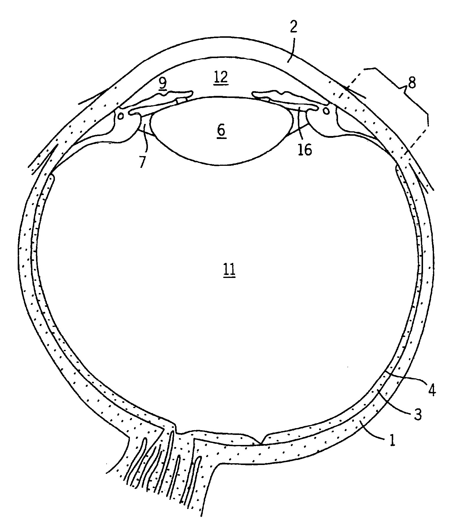
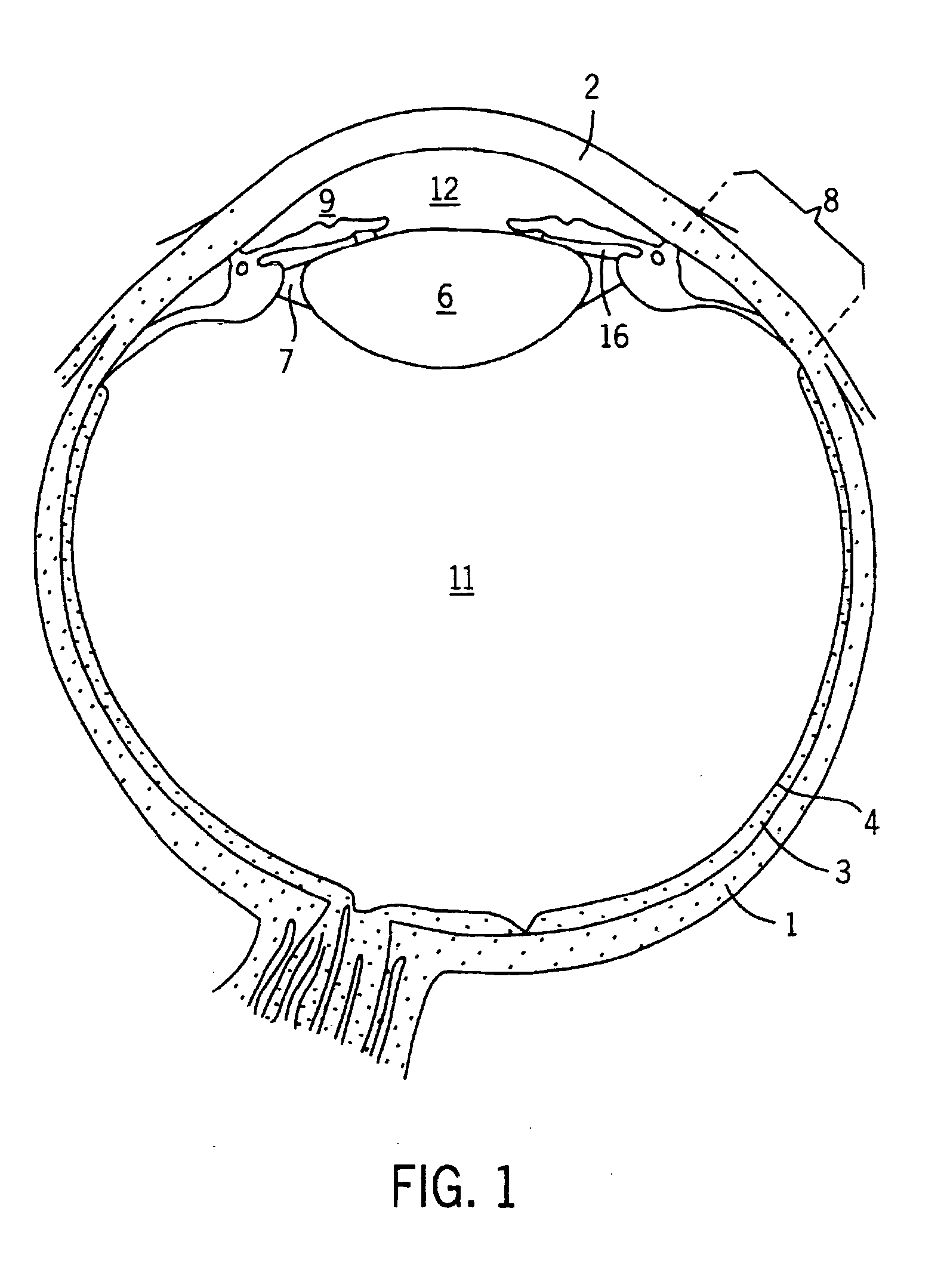
[0041] The major anatomical structures of the eye are shown in FIG. 1. The eye is surrounded by an outer protective layer, the sclera 1. The anterior portion of the sclera 1, the cornea 2, is modified to allow light rays to enter the eye. The choroid 3 resides within the sclera 1 and comprises vasculature which nourishes most of the structures of the eyeball. The posterior portion of the choroid 3 is lined by the retina 4. The retina 4 is composed of the neural tissue containing the receptor cells that receive and process the incoming light rays.

[0042]FIG. 1 also illustrates several other structures of the eye, particularly those areas to be affected by the pump assembly of the invention, generally indicated by the numeral 10. The transparent, biconvex lens 6, one of the refractive media of the eye, is secured by the lens ligament 7 to the ciliary body 8. The ciliary body 8 is the thickened anterior portion of the choroid 3. The iris 9, the “colored” portion of the eye, lies in fro...


PUM


Abstract

An implantable, miniature pump assembly having a flexible elastic bladder actuating assembly. The bladder, in the non-flexed state, has an elongated, substantially rectangular profile, with a predetermined internal volume or capacity. Influent and effluent conduits extend in opposite directions from respective end portions of the bladder. Each of the conduits include one way valves disposed therein to limit fluid flow to a single direction into and through the bladder. Contraction and expansion of the bladder by means of energy harvested from the dynamic environment in which it is implanted in response to ambient random dynamic motion creates alternating pressure and vacuum within the bladder, alternately drawing fluid into the bladder through the influent conduit, and forcing fluid from the bladder via the effluent conduit. The bladder pump assembly harvests its operational energy from the random dynamic motion of the surrounding organs and tissues and therefore does not require an internal or external power source.

Description


Claims


Application Information

Patent Timeline
Owner SOLTANPOUR DAVID P
Why Eureka
Try Eureka