Actuator exhaust fluid energy harvester

a technology of exhaust fluid and energy harvester, which is applied in the direction of mechanical equipment, machines/engines, transportation and packaging, etc., can solve the problems of loss of energy, loss of energy, and degrade the efficiency of the system, and achieve the effect of greater efficiencies of the motive system

Active Publication Date: 2018-09-11
PHD
View PDF36 Cites 0 Cited by
  • Summary
  • Abstract
  • Description
  • Claims
  • Application Information

AI Technical Summary

Benefits of technology

[0010]An advantage of the present invention is that greater efficiencies of a motive system can be achieved.
[0011]Another advantage of the present invention is that harvested energy which would have been lost in a traditional motive system can be stored or used to perform work elsewhere in the motive system.
[0012]Yet another advantage of the present invention is that motion of the actuator can be controlled while simultaneously harvesting energy from the exhaust fluid.

Problems solved by technology

As the fluid is exhausted to the low pressure environment or other low pressure sump, the potential energy stored in the compressed fluid is lost from the motive system.
This loss of energy degrades the efficiency of the system.

Method used


Image

  • Actuator exhaust fluid energy harvester
  • Actuator exhaust fluid energy harvester
  • Actuator exhaust fluid energy harvester

Examples


first embodiment

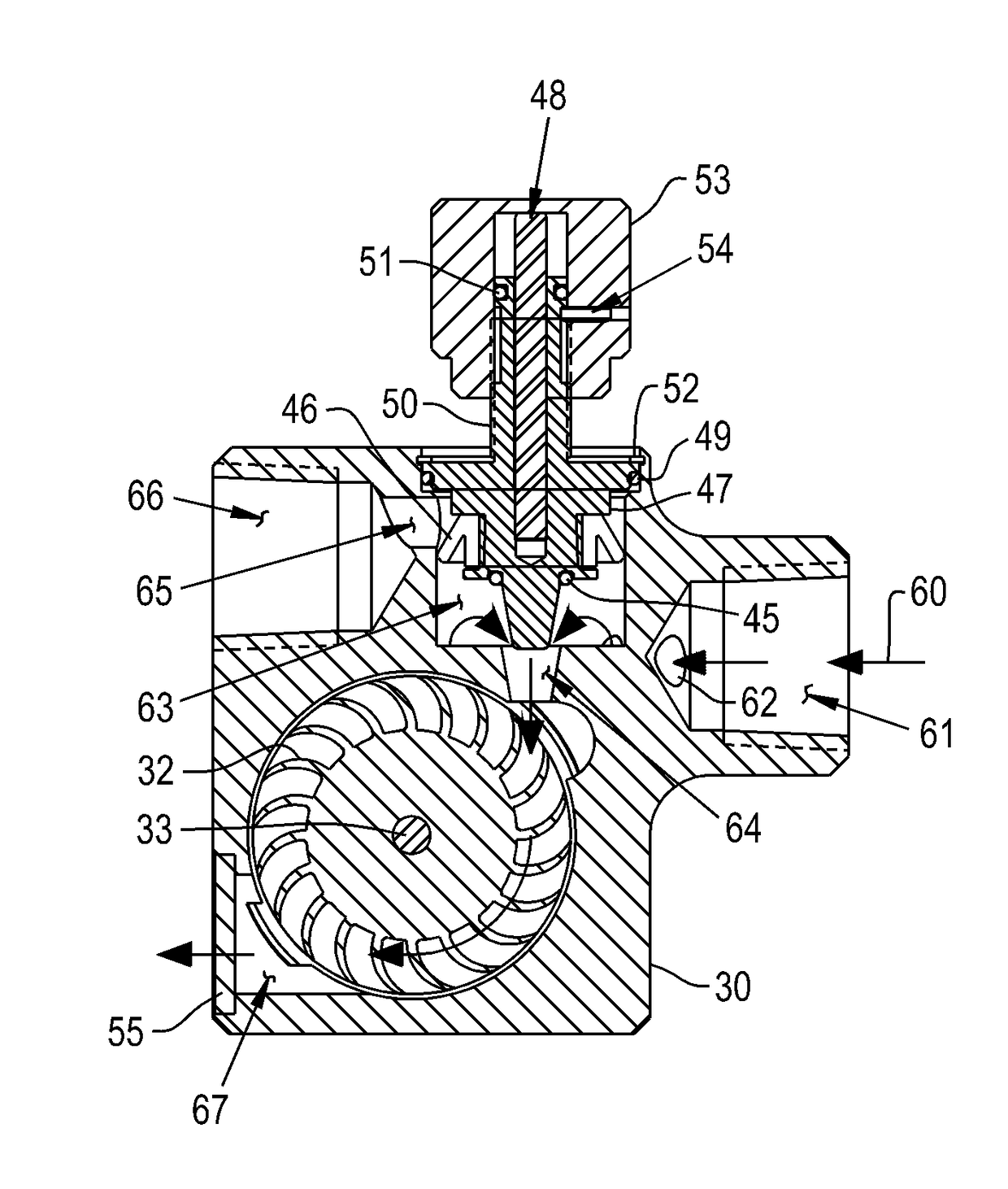
[0047]FIG. 5 shows an exploded isometric view, and FIGS. 7 and 9 show section views, of energy harvester 20, intended to be located between port 6B and line 9B as shown in FIG. 3A. Bearing bushing 31 is disposed into a mating bore in housing 30. Shaft 33 is bonded to turbine 32 so that rotation of turbine 32 causes a like rotation of shaft 33, with one end of shaft 33 supported by bearing bushing 31. The opposing end of shaft 33 is supported by bearing bushing 34. Bushing 34 is disposed into a mating bore in plug 36. The actions of bearing bushings 31 and 34 allow shaft 33 and turbine 32 to rotate freely, while preventing axial translation of the shaft 33 and turbine 32 between plug 36 and housing 30. O-ring seal 35 seals the periphery of plug 36 to prevent the ingress of moisture past the plug 36. The input shaft of electrical generator 37 is bonded to one end of shaft 33 so that rotation of the shaft 33 by turbine 32 causes a like rotation of the generator input shaft. The electri...

second embodiment

[0051]FIG. 12 shows an exploded isometric view, and FIGS. 14 and 16 show section views, of the energy harvester 20, suitable for attachment to exhaust port 11 of valve 10 as shown in FIG. 3B. Bearing bushing 131 is disposed into a mating bore in housing 130. Shaft 133 is bonded to turbine 132 so that rotation of turbine 132 causes a like rotation of shaft 133, with one end of shaft 133 supported by bearing bushing 131. The opposing end of shaft 133 is supported by bearing bushing 134. Bushing 134 is disposed into a mating bore in plug 136. The actions of bearing bushings 131 and 134 allow shaft 133 and turbine 132 to rotate freely, while preventing axial translation of the shaft 133 and turbine 132 between plug 136 and housing 130. O-ring seal 135 seals the periphery of plug 136 to prevent the ingress of moisture past the plug 136. The input shaft of electrical generator 137 is bonded to one end of shaft 133 so that rotation of the shaft 133 by turbine 132 causes a like rotation of ...

third embodiment

[0055]FIG. 17 shows an exploded isometric view, and FIGS. 18 and 19 show section views, of the energy harvester 20, suitable for attachment to exhaust port 11 of valve 10 as shown in FIG. 3B. Such an embodiment may be desirable as a lower cost alternative for those applications wherein optimization of the harvested energy is not required. Bearing bushing 231 is disposed into a mating bore in housing 230. Shaft 233 is bonded to turbine 232 so that rotation of turbine 232 causes a like rotation of shaft 233, with one end of shaft 233 supported by bearing bushing 231. The opposing end of shaft 233 is supported by bearing bushing 234. Bushing 234 is disposed into a mating bore in plug 236. The actions of bearing bushings 231 and 234 allow shaft 233 and turbine 232 to rotate freely, while preventing axial translation of the shaft 233 and turbine 232 between plug 236 and housing 230. O-ring seal 235 seals the periphery of plug 236 to prevent the ingress of moisture past the plug 236. The ...


PUM


Abstract

A fluid energy harvester, including a housing having at least one port and an outlet, and the housing defining at least one fluid passageway therein. The fluid energy harvester also includes a converter disposed within the housing and configured to convert at least a portion of potential energy in an exhaust fluid, a generator operably coupled to the converter and configured to generate an electrical current from the converter, a charging controller electrically coupled to the generator, and a storage medium electrically coupled to the generator and configured to store the electrical current generated by the generator. The fluid energy harvester further includes a nozzle configured to control a flow of the exhaust fluid.

Description

CROSS REFERENCE TO RELATED APPLICATIONS[0001]This is a non-provisional application based upon U.S. provisional patent application Ser. No. 62 / 314,527, entitled “ACTUATOR EXHAUST FLUID ENERGY HARVESTER”, filed Mar. 29, 2016, which is incorporated herein by reference.BACKGROUND OF THE INVENTION1. Field of the Invention[0002]The present invention relates to energy harvesters, and, more particularly, to an exhaust fluid energy harvester in a motive system that generates electrical energy in order to store the electrical energy and / or use it to power an external load.2. Description of the Related Art[0003]Actuators are mechanical or electromechanical devices which convert energy into mechanical motion. Often, mechanical actuators are powered with a compressed fluid which alternately enters and exits a cylindrical volume to act against a movable piston and rod assembly. The rod is extended by fluid pressure acting on one face of the piston and is retracted when fluid acts on the opposing ...

Claims


Application Information

Patent Timeline
Patent Type & Authority Patents(United States)
IPC IPC(8): H02K7/18F03B1/04F03B13/00F03B1/00F01B31/28F01B1/01F01N5/04H02J7/00
CPCH02K7/1823F01B1/01F01B31/28F01N5/04F03B1/04F03B13/00H02J7/0068F03B1/00F05B2240/2411F05B2220/602Y02B10/50Y02E10/20
Inventor PRICE, NICOLE M.WILLIAMS, MATTHEW R.
Owner PHD
Why Eureka
Try Eureka