
Self-burying sediment energy harvester

a sediment energy harvester and self-burying technology, applied in the direction of biochemical fuel cells, etc., can solve the problem of limited effective deployment life of sediment energy harvesters, their persistence is typically limited

Active Publication Date: 2016-11-15
THE UNITED STATES OF AMERICA AS REPRESENTED BY THE SECRETARY OF THE NAVY
View PDF5 Cites 0 Cited by
  • Summary
  • Abstract
  • Description
  • Claims
  • Application Information

AI Technical Summary

Benefits of technology

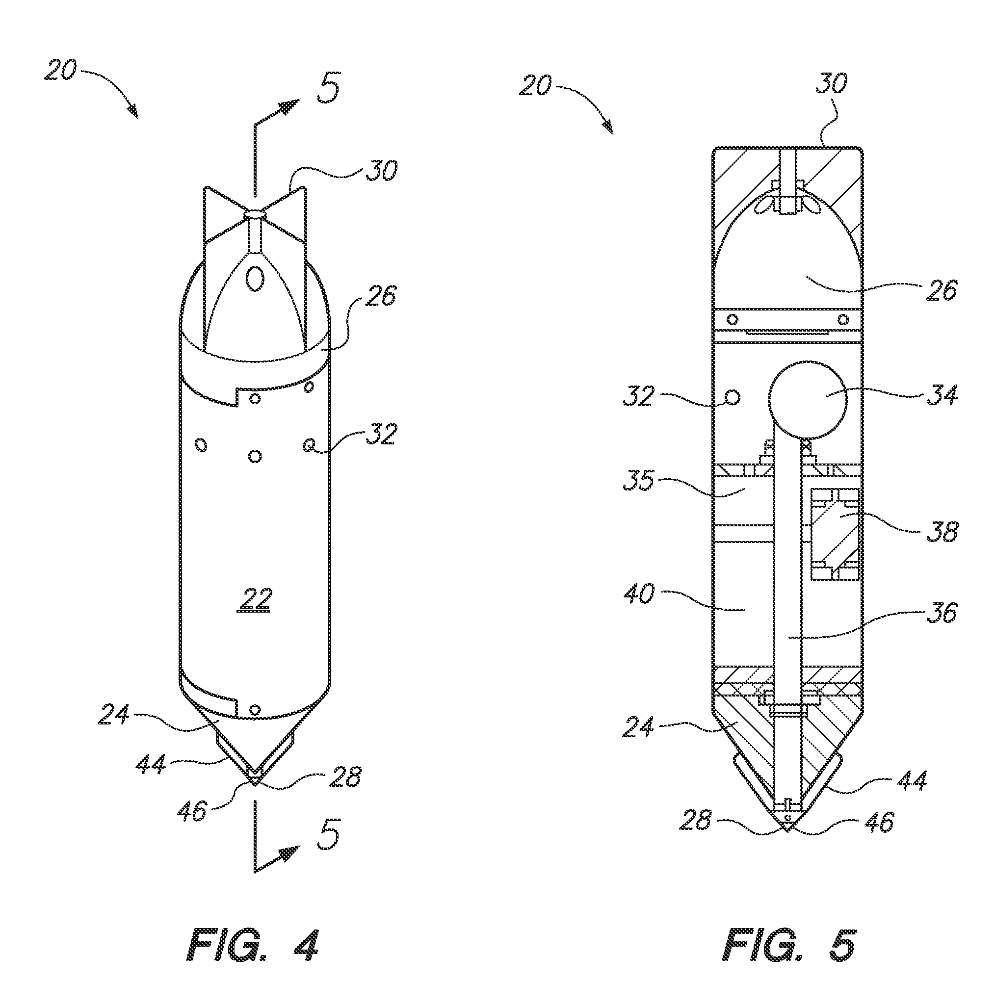
[0008]A microbial fuel cell in accordance with several embodiments of the present invention can include a housing with an integrated anode, cathode and internal conductor and electronics. An anode can be integrated into the housing at the housing proximal end, and a cathode can be integrated into the housing at the distal end. The housing can incorporate a conductor and harvesting electronics in the mid-section located between the cathode and the anode. The housing can be made from a material that does not easily corrode in a seawater environment. The mid-section of the housing can serve as a means of isolating the anode from the cathode and thus maintaining the MFC potential, while also incorporating internal conductors and electronics that can harvest the energy from the MFC. The buried anode portion of the housing can be constructed from non-corroding, conductive materials such as titanium, platinum, graphite, activated carbon, carbon fiber, or other carbon nanomaterial.

Problems solved by technology

Once seafloor systems, such as the self-burying system described here, have been deployed, their persistence (effective deployment life) is typically limited by the finite energy of an enclosed battery.

Method used


Image

  • Self-burying sediment energy harvester
  • Self-burying sediment energy harvester
  • Self-burying sediment energy harvester

Examples


Embodiment Construction

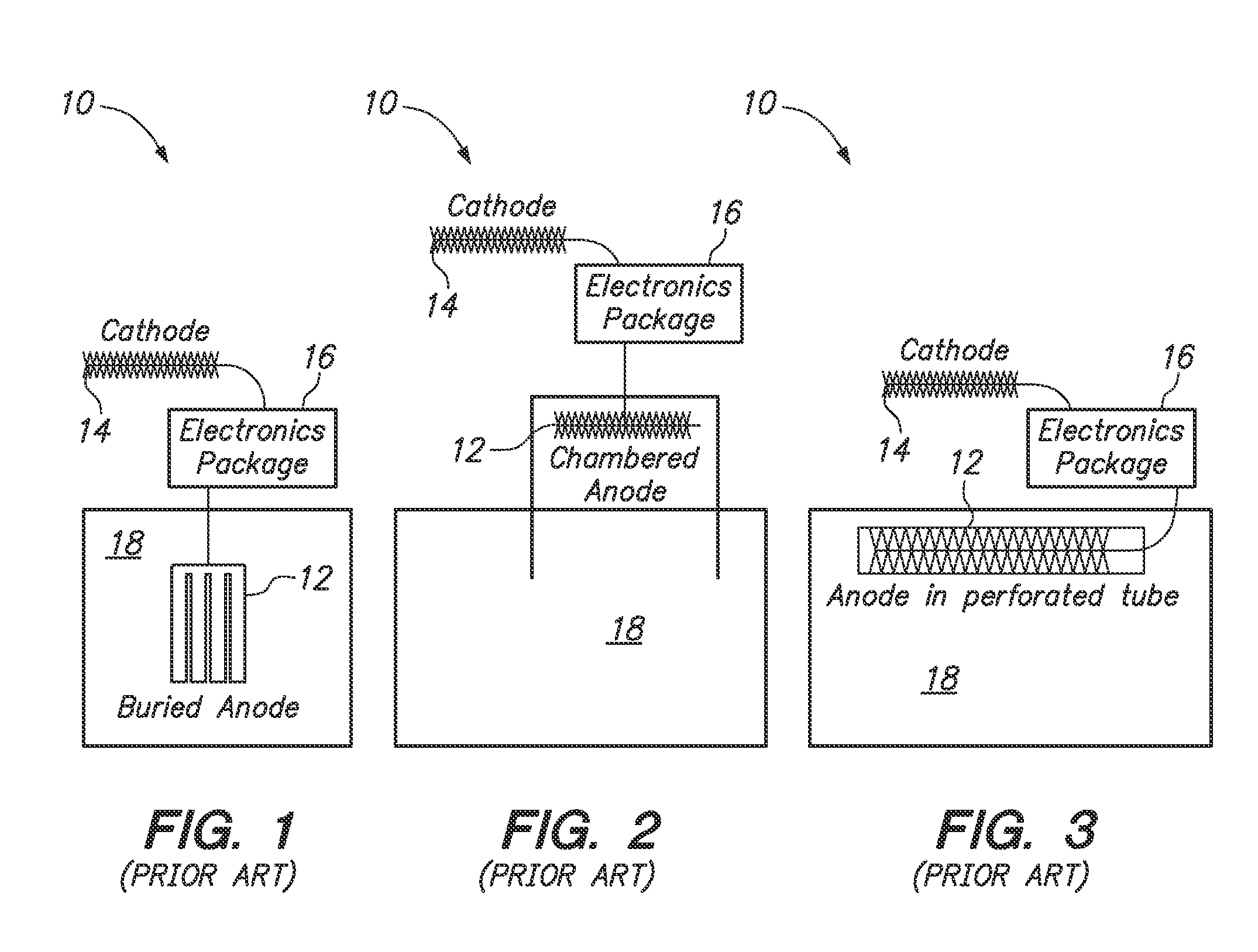
[0020]Referring initially to FIGS. 1-3, a microbial fuel cell as known in the prior art is shown an illustrated by reference character 10. As shown, microbial fuel cell (MFC) 10 can include an anode 12 which is buried in or in contact with sediment 18, a cathode 14 and an electronics package 16. FIGS. 2-3 illustrate an MFC 10 utilizing a “bottlebrush electrode” as the anode 12 and / or cathode 14, and in FIG. 3 the anode 12 resides in a permeable tube. It is unclear whether this device could be a self-deployable system or if the system could require divers or submersibles to position the electrodes. But in general, the prior art benthic MFC designs shown in FIGS. 1-3 have generally required manual placement of the anode 12 and cathode 14 in appropriate positions at the sediment-water interface, using divers, underwater sleds or some combination thereof.

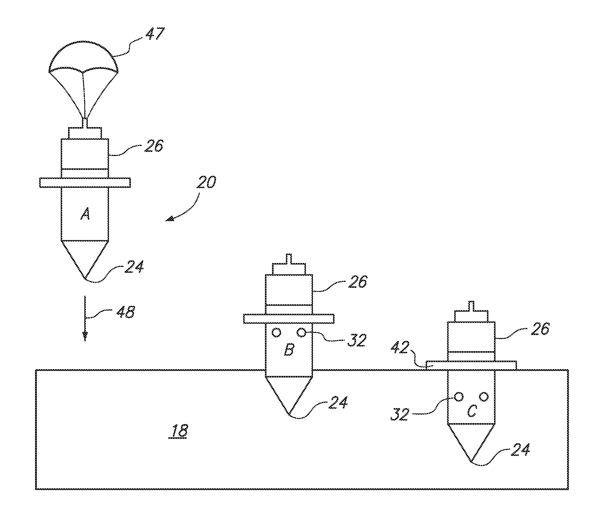
[0021]Referring now to FIGS. 4-5, a self-burying MFC 20 of the present invention according to several embodiments is shown and is gene...


PUM

PropertyMeasurementUnit
conductiveaaaaaaaaaa
chemical energyaaaaaaaaaa
electrical energyaaaaaaaaaa

Abstract

A self-burying microbial fuel cell can include a housing with conductive elements. An anode and cathode can be integrated into the housing at respective proximal and distal ends. A self-burying means for partially burying the microbial fuel cell in a submerged environment is included, so that the anode is buried but the cathode is exposed to the submerged environment can be included. The self-burying means can include omni-directional vibrating device located within the housing, a plurality of intake ports formed in the housing for a pump within the housing. The pump outputs into a longitudinal fluid conduit that extends through the housing and exits at the distal end of the housing. When the vibrating device activates at the same time as the pump, temporary slurry can be formed at the extreme distal end of the device, and the vibrating action causes the microbial fuel cell to become partially buried.

Description

FEDERALLY-SPONSORED RESEARCH AND DEVELOPMENT[0001]The United States Government has ownership rights in this invention. Licensing inquiries may be directed to Office of Research and Technical Applications, Space and Naval Warfare Systems Center, Pacific, Code 72120, San Diego, Calif., 92152; telephone (619) 553-5118; email: ssc pac t2@nav.mil, referencing NC 101761.FIELD OF THE INVENTION[0002]The present invention pertains generally to microbial fuel cells. More specifically, the present invention pertains to microbial fuel cells that are self-burying for ease of deployment and more survivable in an ocean environment (attributed to ability to anchor), and that have an internal power supply to maximize the deployment cycle for the microbial fuel cell.BACKGROUND OF THE INVENTION[0003]Fuel cells are well known in the prior art. A fuel cell differs from a battery in that it is a thermodynamically open system where the fuel source reactant is continuously supplied from an external source....

Claims


Application Information

Patent Timeline
Patent Type & Authority Patents(United States)
IPC IPC(8): H01M8/16
CPCH01M8/16Y02E60/527Y02E60/50
Inventor ARIAS-THODE, YOLANDA MERIAHHSU, LEWISBIANCHI, JOSHUAHALONEN, RYAN JOHNCHADWICK, BART
Owner THE UNITED STATES OF AMERICA AS REPRESENTED BY THE SECRETARY OF THE NAVY
Learn More