Contact Interface Energy Harvesting Systems and Methods

a technology of energy harvesting system and contact interface, which is applied in the direction of machines/engines, flexible member pumps, and positive displacement liquid engines, etc., can solve the problem of additional design/implementation constraints relating to the preexisting purpose of cushioning suppor

Inactive Publication Date: 2016-02-04
KLOTZER DANIEL
View PDF2 Cites 1 Cited by
  • Summary
  • Abstract
  • Description
  • Claims
  • Application Information

AI Technical Summary

Benefits of technology

[0009]A large variety of embodiments of the present invention are implementable, with an almost unlimited number of variations, permutations, and cross-combinations of differing aspects of other embodiments potentially integrable in other embodiments. Many embodiments employing some of the systems and methods of the present invention involve at least one fluid fillable volume which is subject to recurrent, but not generally static, boundary forcing. The volume is at least partially enclosed by a responsive boundary, wherein the term responsive indicates that the enclosing boundary is responsive to the boundary forcing and/or the boundary forcing's effect upon the fluid fill. The boundary forcing is generally driven by circumstances that exist regardless of the energy harvesting operations, though those operations can and often do t

Problems solved by technology

One significant consequence of this difference is that when there is a preexisting purpose for the presence of the cushioning support, additional design/implementation constraints related to the preexisting purpose for the cushioning support are likely.
Tire exteriors integrated with the inflatable bladder present both greater ranges of energy harvesting techniques that can be employed (because energy harvesting technique

Method used


Image

  • Contact Interface Energy Harvesting Systems and Methods
  • Contact Interface Energy Harvesting Systems and Methods
  • Contact Interface Energy Harvesting Systems and Methods

Examples


Embodiment Construction

[0105]In the following description, identical numbers indicate identical elements. Where an element has been described in one Figure, and is unaltered in detail or relation in any other Figure, said element description applies to all Figures. In most of the descriptions of the embodiments, the drawings should be considered as schematic and not necessarily describing dimensions to scale or realistic detail, unless the description specifically and expressly does describe exact dimensions, relative dimensions, or particular details.

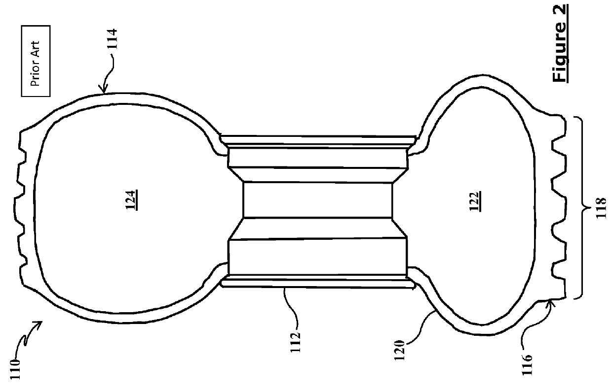
[0106]In FIG. 1 is depicted a cross-section view of a typical legacy tire 110 construction showing a wheel 112 and a tire 114. The tire 110 rides on a tread 116 that, when a contact patch 118 portion of the tread 116 is forced towards the wheel 112 compresses and alters the cross-section of the supporting tire section volume 122, as compared to a non-supporting tire section volume 124. The supporting volume 122, in comparison to the non-supporting volume 124...


PUM


Abstract

The present invention is an energy harvesting contact interface usable as a vehicle tire or a cushion, among other purposes.

Description

CROSS-REFERENCE TO RELATED APPLICATIONS[0001]The present application is a continuation of and claims priority to prior PCT application no. PCT / US2014 / 030084, filed on Mar. 15, 2014, and prior applications U.S. provisional patent application No. 61 / 791,431, filed on Mar. 15, 2013, and U.S. provisional patent application No. 61 / 953,709, filed on Mar. 14, 2014, all invented by Daniel Klotzer, and the entirety of the disclosures of the three prior applications are explicitly incorporated herein by reference.STATEMENT REGARDING FEDERALLY SPONSORED RESEARCH OR DEVELOPMENT[0002]Not applicable.BACKGROUND OF THE INVENTION[0003]1. Field of the Invention[0004]The present invention relates generally to systems and methods of harvesting energy from externally applied compressional forces, and in particular to utilizing recurrently occurring contact interface and / or compressional forces to harvest energy, said forces often acting on fluid filled (including inflated) volumes.[0005]2. Related Art[0...

Claims


Application Information

Patent Timeline
IPC IPC(8): F03G7/08F04B45/04
CPCF04B45/04F03G7/08Y02T10/7072
Inventor KLOTZER, DANIEL
Owner KLOTZER DANIEL
Why Eureka
Try Eureka