Flow-through sound-cancelling mufflers

a flow-through, sound-cancelling technology, applied in the field of mufflers, can solve the problems of back-pressure exerted on the engine, increase fuel consumption, and reduce engine performance, and achieve the effect of reducing engine load

Inactive Publication Date: 2007-05-17
SULLIVAN JOHN TIMOTHY
View PDF44 Cites 51 Cited by
  • Summary
  • Abstract
  • Description
  • Claims
  • Application Information

AI Technical Summary

Benefits of technology

[0016] It is a first objection of the invention to provide a muffler that reduces engine load.
[0017] It is a second objective of the invention to provide a muffler that effectively cancels a broad spectrum exhaust noise frequencies.
[0018] It is a third objective of the invention to provide a muffler that may easily be adapted for a particular acoustic profile.

Problems solved by technology

However, the material through which the gases are passed inherently cause back-pressure to be exerted on the engine.
Excess back-pressure increases fuel consumption and decreases engine performance.
While these flow-through mufflers have the effect of reducing back-pressure on the engine, however, they are relatively expensive to manufacture and have not achieved widespread use, except in specialty applications.
The reason is that they are relatively complicated to construct, and only cancel a limited range of frequencies.
The sound cancelling muffler disclosed in U.S. Pat. No. 6,296,074 utilizes an especially complex structure, which not only is expensive to construct but also takes up a relatively large volume.

Method used


Image

  • Flow-through sound-cancelling mufflers
  • Flow-through sound-cancelling mufflers
  • Flow-through sound-cancelling mufflers

Examples


Embodiment Construction

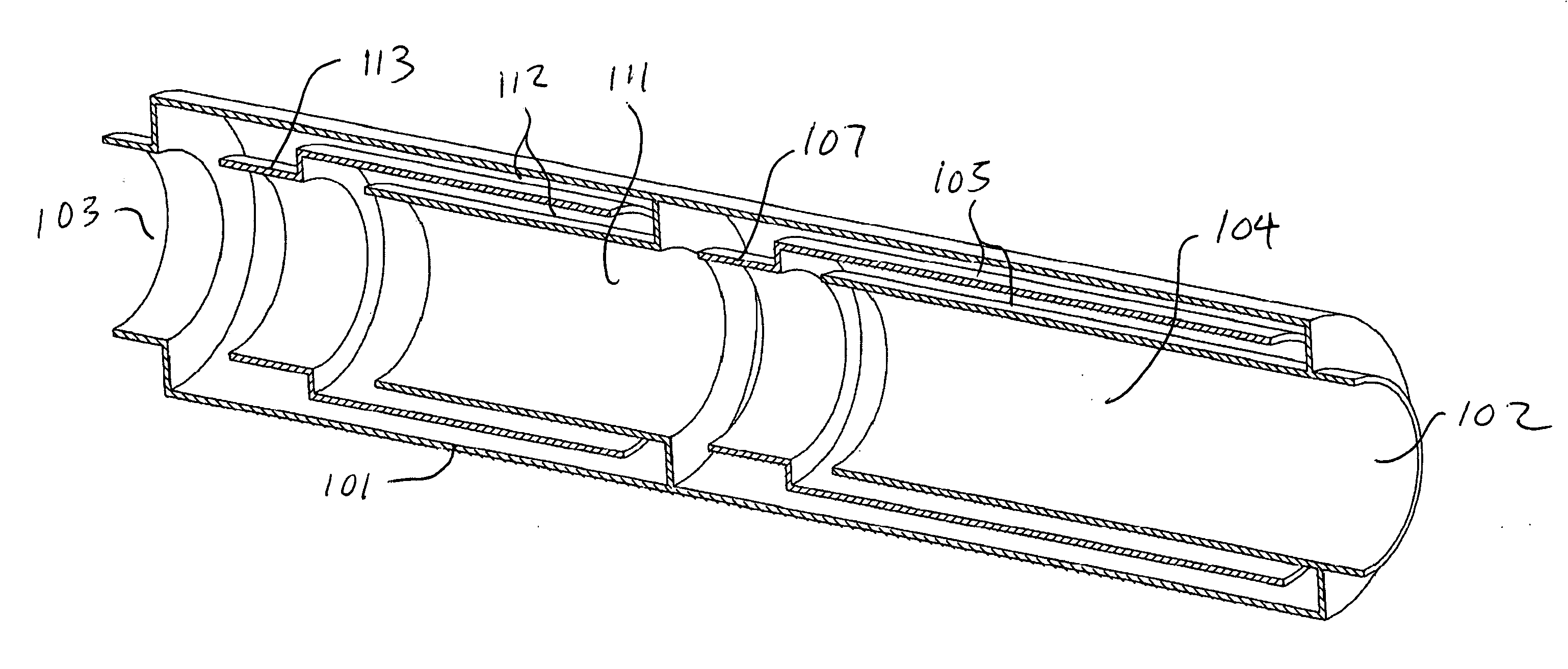
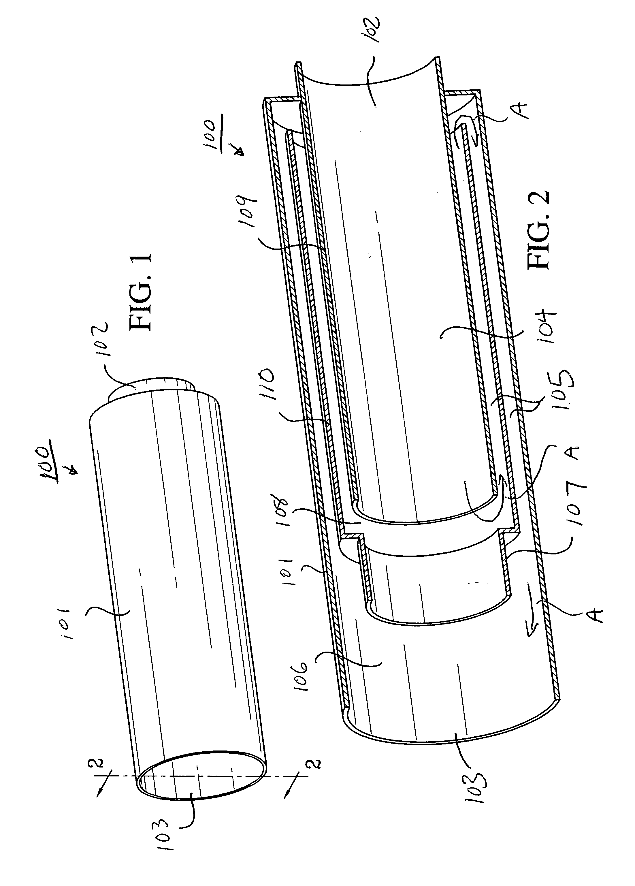
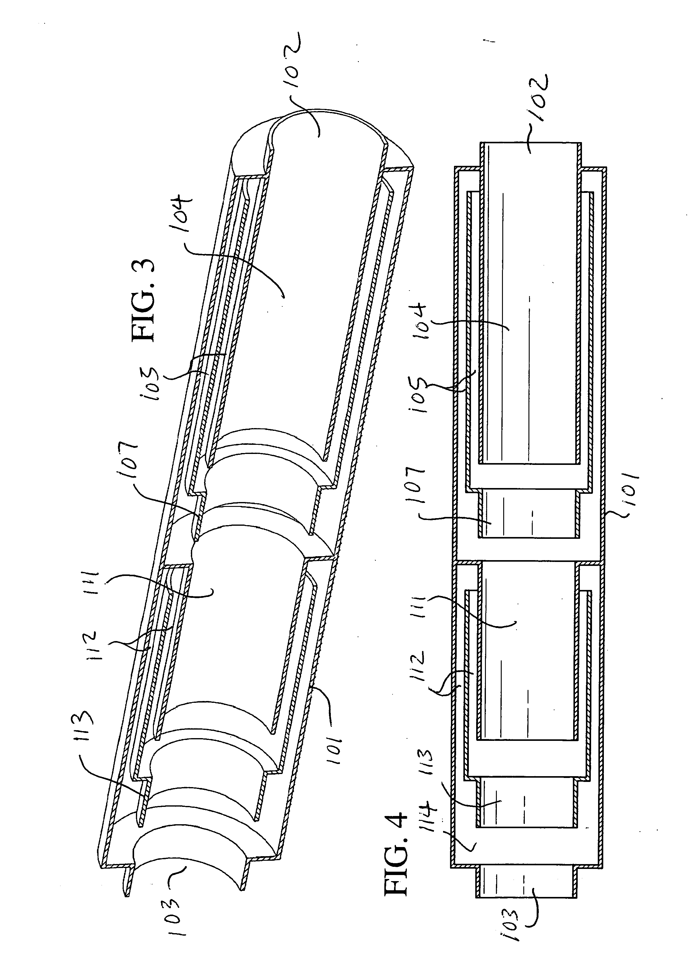
[0046]FIGS. 1 and 2 illustrate a flow-through sound-cancelling muffler 100 constructed in accordance with the principles of a first preferred embodiment of the invention. Muffler 100 includes a housing 101 having an inlet 102 and outlet 103, and arranged to form an inner passage 104, an outer passage 105, and a sound cancellation or conversion chamber 106.

[0047] Outer passage 105 is situated between the inner passage and an exterior wall of the housing 101, and surrounds the inner passage. In order to provide a difference in path lengths between the inner and outer passages, outer passage 105 has a zigzag shape, i.e., it begins at an opening 108 on the downstream side of the inner passage 104, extends back toward the inlet side of the inner passage along the outside of a cylindrical wall defining the inner passage, and then reverses direction and extends back toward the outlet side of the inner passage along an outer wall of the housing 101, finally opening into or communicating wi...


PUM


Abstract

A sound-cancelling flow-through muffler includes a linear first inner passage, and a curved or zig-zagged second outer passage that wraps around or surrounds the inner passage and that is situated between the linear first inner passage and an exterior wall of the muffler. The outer passage has a length that is equal to, or a multiple of, one-half the wavelength of sound to be cancelled by the muffler such that sound exiting the inner and outer passages destructively interferes or cancels in a sound cancellation or conversion chamber. In addition, the walls of the outer passage serve as a heat sink to extract heat from the exhaust stream and conduct the heat to the outside of the housing. Alternatively, the outer passage may have a closed such that reflects sound back toward the inner passage for cancellation, the walls of the outer passage continuing to serve as a heat sink to extract heat from the exhaust stream and conduct the heat to the outside of the housing.

Description

BACKGROUND OF THE INVENTION [0001] 1. Field of the Invention [0002] This invention relates to mufflers, and in particular to high efficiency, sound-cancelling flow-through mufflers arranged to reduce fuel consumption by decreasing back-pressure and therefore load on an engine. [0003] In a first set of preferred embodiments, the mufflers feature a linear inner passage and a curved or zig-zag shaped outer passage that wraps around or surrounds the inner passage and is situated between the inner passage and an exterior wall of the muffler. The outer passage has a length that equals one-half the wavelength of sound to be canceled, or multiples of one-half wavelength, such that sound waves exiting the outer passage destructively interferes with or cancels sound waves directly exiting the inner passage to a sound-cancellation or conversion chamber at the outlet of the passages. [0004] In a second set of preferred embodiments, the mufflers feature a linear inner passage and a curved or zig...

Claims


Application Information

Patent Timeline
Patent Type & Authority Applications(United States)
IPC IPC(8): F01N1/02
CPCF01N1/06F01N3/02F01N5/025F01N2470/24H01L35/30Y02T10/16Y02T10/12H10N10/13
Inventor SULLIVAN, JOHN TIMOTHY
Owner SULLIVAN JOHN TIMOTHY
Why Eureka
Try Eureka