System and method for reducing fuel consumption in a vehicle

a technology for reducing fuel consumption and vehicles, applied in the field of vehicle control, can solve the problems of increasing fuel consumption, adding to power demand, and increasing fuel consumption, and achieve the effect of reducing fuel consumption and improving the overall efficiency of electric drive machines

Active Publication Date: 2018-02-13
GE GLOBAL SOURCING LLC
View PDF15 Cites 3 Cited by
  • Summary
  • Abstract
  • Description
  • Claims
  • Application Information

AI Technical Summary

Benefits of technology

[0011]In another embodiment, a drive system for a vehicle includes an engine, an alternator coupled to the engine, and a traction motor system. The alternator is configured to power at least one auxiliary load. The traction motor system is operatively coupled to drive wheels of the vehicle, and is configured for receiving primary electrical power from the alternator and for propelling the vehicle in response to the primary electrical power. The drive system further includes a three-phase inverter / rectifier electrically connected to the traction motor system and to the alternator. The inverter / rectifier is configured to receive electrical power from the traction motor system in a dynamic braking mode of operation of the traction motor system and to feed the electrical power to the alternator as torque to reduce engine load.
[0012]In yet another embodiment, a method is provided. The method includes the steps of generating primary electrical power at an alternator connected to an engine, operating a traction motor coupled in driving relationship to a wheel of a vehicle to propel the vehicle during a propel mode of operation and to generate electricity during a dynamic braking mode of operation, wherein in the propel mode of operation the primary electrical power is transmitted to the traction motor to power the motor, and utilizing the electricity generated during the dynamic braking mode of operation to offset an auxiliary engine load to decrease fuel consumption of the vehicle (e.g., versus an operating mode where electricity generated during dynamic braking is not used to offset an auxiliary engine load).

Problems solved by technology

A drawback to this, however, is that a grid cooling system having an electrically driven blower is often necessary to help dissipate heat from the grid, which adds to power demand and thus increases fuel consumption.
Even during dynamic braking, the engine continues to consume fuel to meet the electrical needs and auxiliary loads of the vehicle.

Method used


Image

  • System and method for reducing fuel consumption in a vehicle
  • System and method for reducing fuel consumption in a vehicle
  • System and method for reducing fuel consumption in a vehicle

Examples


Embodiment Construction

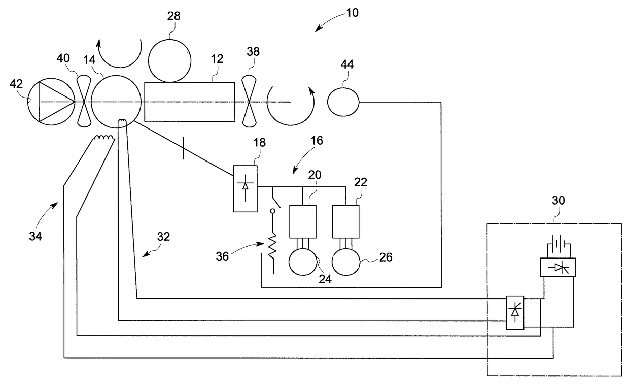
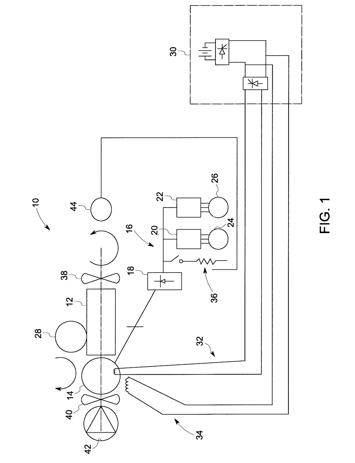
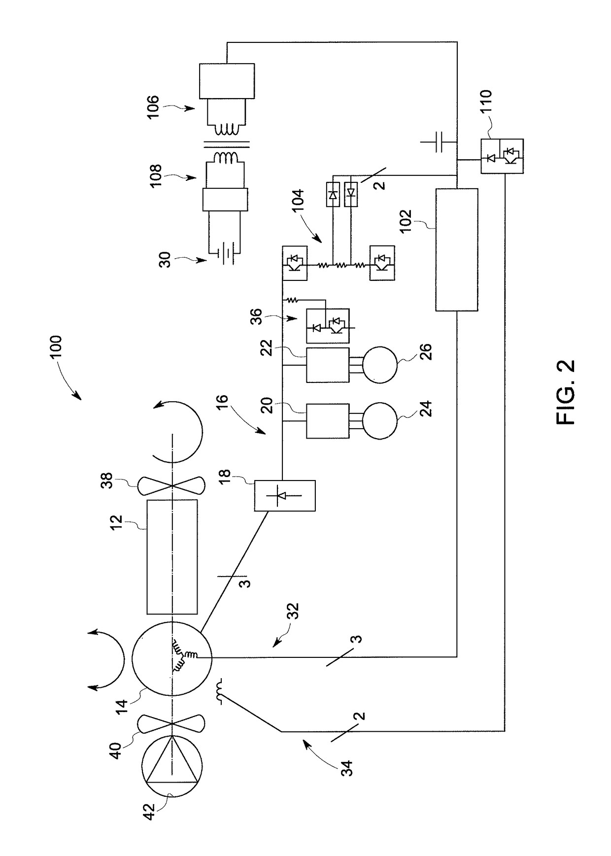
[0019]Reference will be made below in detail to exemplary embodiments of the invention, examples of which are illustrated in the accompanying drawings. Wherever possible, the same reference characters used throughout the drawings refer to the same or like parts. While embodiments of the invention are suitable for use with both mobile and stationary implementations, for ease of explanation a mobile implementation is described in detail herein. More specifically, an OHV has been selected for clarity of illustration for the disclosure of mobile embodiments. Other suitable vehicles include, for example, on-road vehicles, locomotives, construction equipment, industrial equipment, and marine vessels. As used herein, “electrical communication” or “electrically coupled” means that certain components are configured to communicate with one another through direct or indirect signaling by way of direct or indirect electrical connections. As used herein, “mechanically coupled” refers to any coup...


PUM


Abstract

A drive system includes an engine, an alternator coupled to the engine, the alternator being configured to power at least one auxiliary load, a traction motor system operatively coupled to drive wheels of the vehicle, the traction motor system being configured for receiving primary electrical power from the alternator and for propelling the vehicle in response to the primary electrical power, and a motor electrically connected to the traction motor system and mechanically coupled to the engine. The motor is configured to receive electrical power from the traction motor system in a dynamic braking mode of operation of the traction motor system and to communicate power to the engine during the dynamic braking mode.

Description

CROSS-REFERENCE TO RELATED APPLICATIONS[0001]This application is a continuation-in-part of U.S. application Ser. No. 14 / 094,333, filed Dec. 2, 2013, which claims priority to U.S. Provisional Application No. 61 / 732,312 filed Dec. 1, 2012, both of which are incorporated by reference herein in their entireties.BACKGROUND[0002]Technical Field[0003]Embodiments of the invention relate generally to vehicle control. Certain embodiments relate to systems and methods for reducing fuel consumption in a vehicle in a dynamic braking mode of operation.[0004]Discussion of Art[0005]In the mining industry, large off-highway vehicles, “OHVs”, usually employ electrically motorized wheels for propelling or retarding the vehicle. In particular, OHVs typically include a large horsepower diesel engine in conjunction with an alternator, a traction inverter, and wheel drive assemblies housed within the rear tires of the vehicle. In operation, the diesel engine drives the alternator, which powers the tractio...

Claims


Application Information

Patent Timeline
Patent Type & Authority Patents(United States)
IPC IPC(8): F02D41/12B60W30/182B60L7/16B60L11/06F02D29/02B60L7/20F02N11/08B60L50/12
CPCB60L7/20B60L7/16B60W30/182F02D29/02B60L11/06F02N11/0862B60K6/46B60W10/06B60W10/08B60W10/30B60W30/18127B60W20/15B60L50/12Y02T10/62
Inventor WOLFF, JEFFREY JOHNKUMAR, AJITH KUTTANNAIRYOUNG, HENRY TODDKUTTENKULER, JASON DANIELBORISENKO, MAKSIM V.PETRAK, EDWARD
Owner GE GLOBAL SOURCING LLC
Why Eureka
Try Eureka