Vehicle generator control method and system thereof

a generator control and vehicle technology, applied in the direction of electric control, engine starters, machines/engines, etc., can solve the problems of difficult or ineffective starting of vehicles, and achieve the effects of small structure, reduced starting load of engines, and improved cold starting capacity

Active Publication Date: 2020-03-05
GUANGXI YUCHAI MASCH CO LTD
View PDF1 Cites 2 Cited by
  • Summary
  • Abstract
  • Description
  • Claims
  • Application Information

AI Technical Summary

Benefits of technology

[0018]In the present invention, the engine ECU controls the starting and operation of the generator according to the operating condition of the engine, the starting load of the engine can be effectively reduced, and cold starting capacity is improved. In a generator control unit of the present invention, a generator control relay is provided and controlled by the engine ECU, and the starting and operation of the generator can be skillfully controlled, so that the structure is small, costs are saved, and the control precision is improved. In the present invention, a generator control unit and a starter control relay can be interlocked by the engine ECU and a time delay relay can be used, which can effectively improve control precision and accuracy. In the present invention, the first diode is provided to effectively avoid an influence of the reverse voltage generated by the generator excitation coil on the entire circuit. In the present invention, the second diode is provided to prevent instantaneous generation of the reverse voltage due to disconnection of the coil of the generator control relay, thereby avoiding interference on the line diagnosis and control of the starter control relay caused by the influence of the reverse voltage on the engine ECU.

Problems solved by technology

The instantaneous large current load generated by the starting condition of the generator will increase the starting load of the generator and affect the cold starting capacity of a vehicle, resulting in the vehicle being unable to start or difficult to start in cold weather.

Method used


Image

  • Vehicle generator control method and system thereof
  • Vehicle generator control method and system thereof
  • Vehicle generator control method and system thereof

Examples


embodiment 1

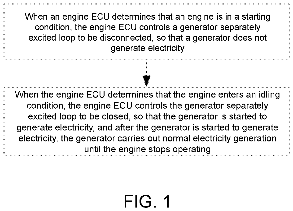
[0025]As shown in FIG. 1 to FIG. 2, the present invention provides a vehicle generator control method. An engine ECU controls the generator according to an operating condition of the engine. A control process is as follows:

[0026]When the engine ECU determines that the engine is in a starting condition, the engine ECU controls a generator separately excited loop 100 to be disconnected, so that the generator does not generate electricity.

[0027]When the engine ECU determines that the engine enters an idling condition, the engine ECU controls the generator separately excited loop 100 to be closed, so that the generator is started to generate electricity, and after the generator is started to generate electricity, the generator carries out normal electricity generation until the engine stops operating.

[0028]The engine ECU determines the operating condition of the engine via an engine speed signal and an engine starting signal, when the engine ECU receives the engine starting signal and t...

embodiment 2

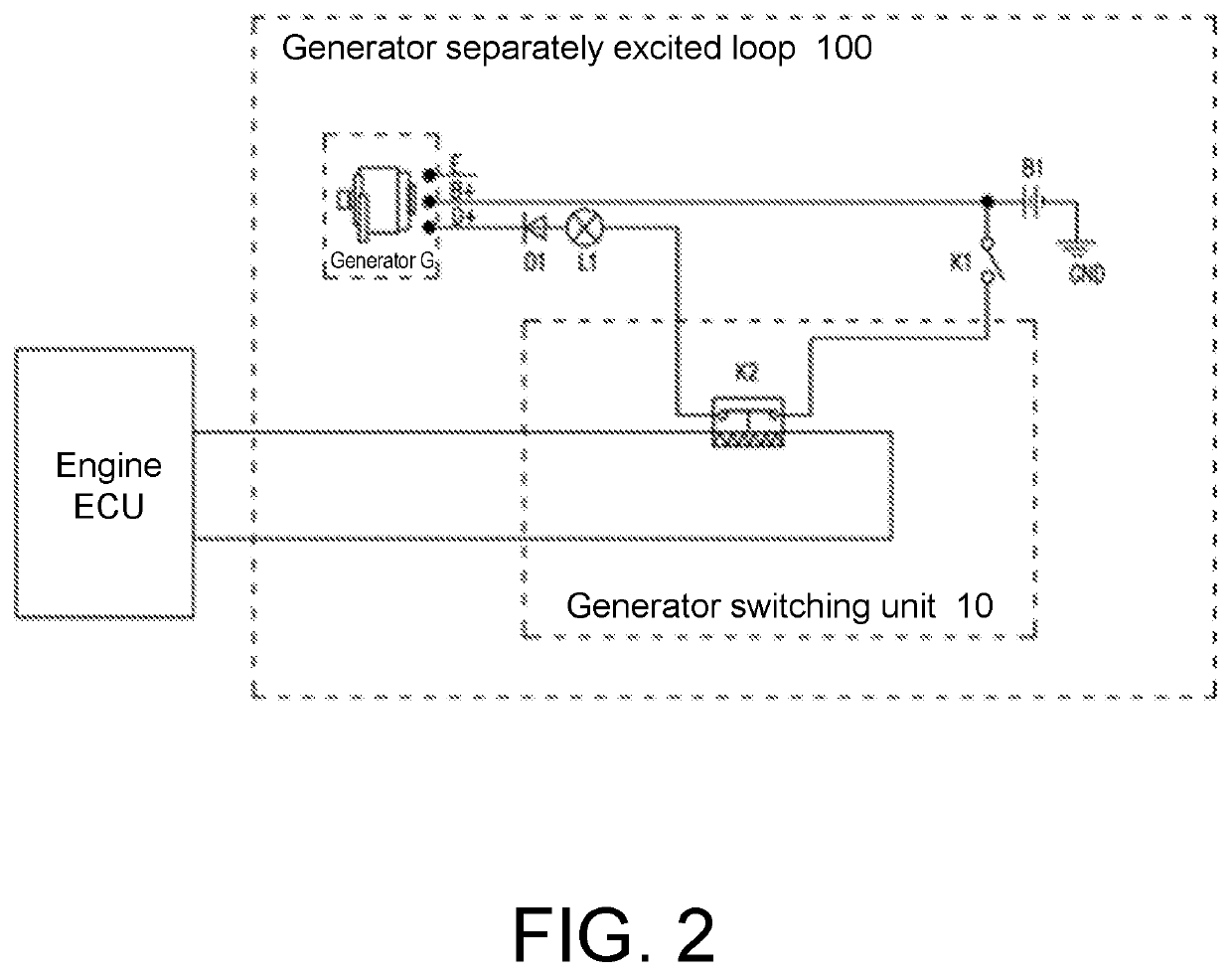
[0031]As shown in FIG. 2, the present invention provides a vehicle generator control system, including an engine ECU and a storage battery B1, and further including a generator switching unit 10 connected using signals to the engine ECU and adapted to carry out ON / OFF control on a generator separately excited loop 100. One end of the generator switching unit 10 is connected to an excitation positive terminal D+ of a generator via a first diode D1 for preventing a generator excitation coil from generating a reverse voltage, and the other end of the generator switching unit 10 is connected to a positive electrode of the storage battery B1 via an ignition switch K1, thereby forming a controllable circuit connecting in series from the positive electrode of the storage battery B1 to the excitation positive terminal D+ of the generator, where a negative electrode of the first diode D1 is connected to the excitation positive terminal D+ of the generator. The positive electrode of the stora...

embodiment 3

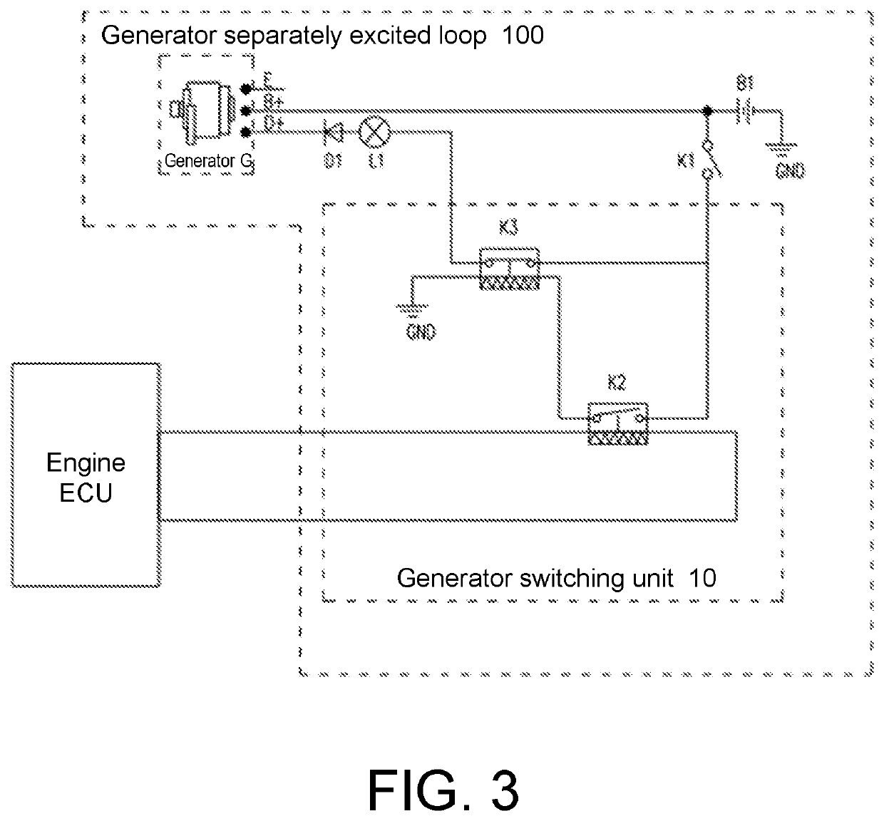
[0035]As shown in FIG. 3, the present invention provides a vehicle generator control system, including an engine ECU and a storage battery B1, and further including a generator switching unit 10 connected using signals to the engine ECU and adapted to carry out ON / OFF control on a generator separately excited loop 100. One end of the generator switching unit 10 is connected to an excitation positive terminal D+ of a generator via a first diode D1 for preventing a generator excitation coil from generating a reverse voltage, and the other end of the generator switching unit 10 is connected to a positive electrode of the storage battery B1 via an ignition switch K1, thereby forming a controllable circuit connecting in series from the positive electrode of the storage battery B1 to the excitation positive terminal D+ of the generator, where a negative electrode of the first diode D1 is connected to the excitation positive terminal D+ of the generator. The positive electrode of the stora...


PUM


Abstract

Provided is a vehicle generator control method. An engine ECU controls the generator according to an operating condition of the engine, and the control process is as follows: when the engine ECU determines that the engine is in a starting condition, the engine ECU controls a generator separately excited loop to be disconnected, so that the generator does not generate electricity; and when the engine ECU determines that the engine enters an idling condition, the engine ECU controls the generator separately excited loop to be closed, so that the generator is started to generate electricity, and after the generator is started to generate electricity, the generator carries out normal electricity generation until the engine stops operating. Through the vehicle generator control method, the starting load of the engine can be effectively reduced, and cold starting capacity is improved. Also provided is a vehicle generator control system.

Description

BACKGROUND OF THE INVENTION1. Field of the Invention[0001]The present invention relates to the field of generator control technologies, in particular, to a vehicle generator control method and a vehicle generator control system.2. Description of Related Art[0002]For a separately excited generator, the generator needs to undergo two processes of separate excitation and self-excitation to generate electricity: in an engine starting condition, that is, a process in which a motor is turned to idle, a generator excitation coil needs to generate an excitation magnetic field by connecting an external current. The process that requires external electric energy to generate or maintain the excitation magnetic field is separate excitation. When a generator speed reaches a certain value, the generator starts to output electric energy while self-supplying an excitation current to maintain the excitation magnetic field, that is, self-excitation. In the existing vehicle control, when an ignition k...

Claims


Application Information

Patent Timeline
Patent Type & Authority Applications(United States)
IPC IPC(8): F02D29/06F02N11/04F02D41/04
CPCF02N11/04B60R16/023F02D29/06F02D41/042F02D41/064F02N11/084F02N11/0862F02N11/087F02N19/001F02N2200/0809Y02T10/40
Inventor XU, XINGJUNZHU, XINBAOZHU, WANNIAN, LIQIANGCHEN, JUNHONGSU, LIYONGCAI, WEIWANG, JIANLONG
Owner GUANGXI YUCHAI MASCH CO LTD
Why Eureka
Try Eureka