Display apparatus and display element driving method
a technology of display elements and apparatus, applied in the direction of instruments, static indicating devices, etc., can solve the problems of remarkably reducing luminance, unable to obtain clear display with sufficient contrast, and unable to obtain stably a long period of time with a high luminance display
- Summary
- Abstract
- Description
- Claims
- Application Information
AI Technical Summary
Benefits of technology
Problems solved by technology
Method used
Image
Examples
first embodiment
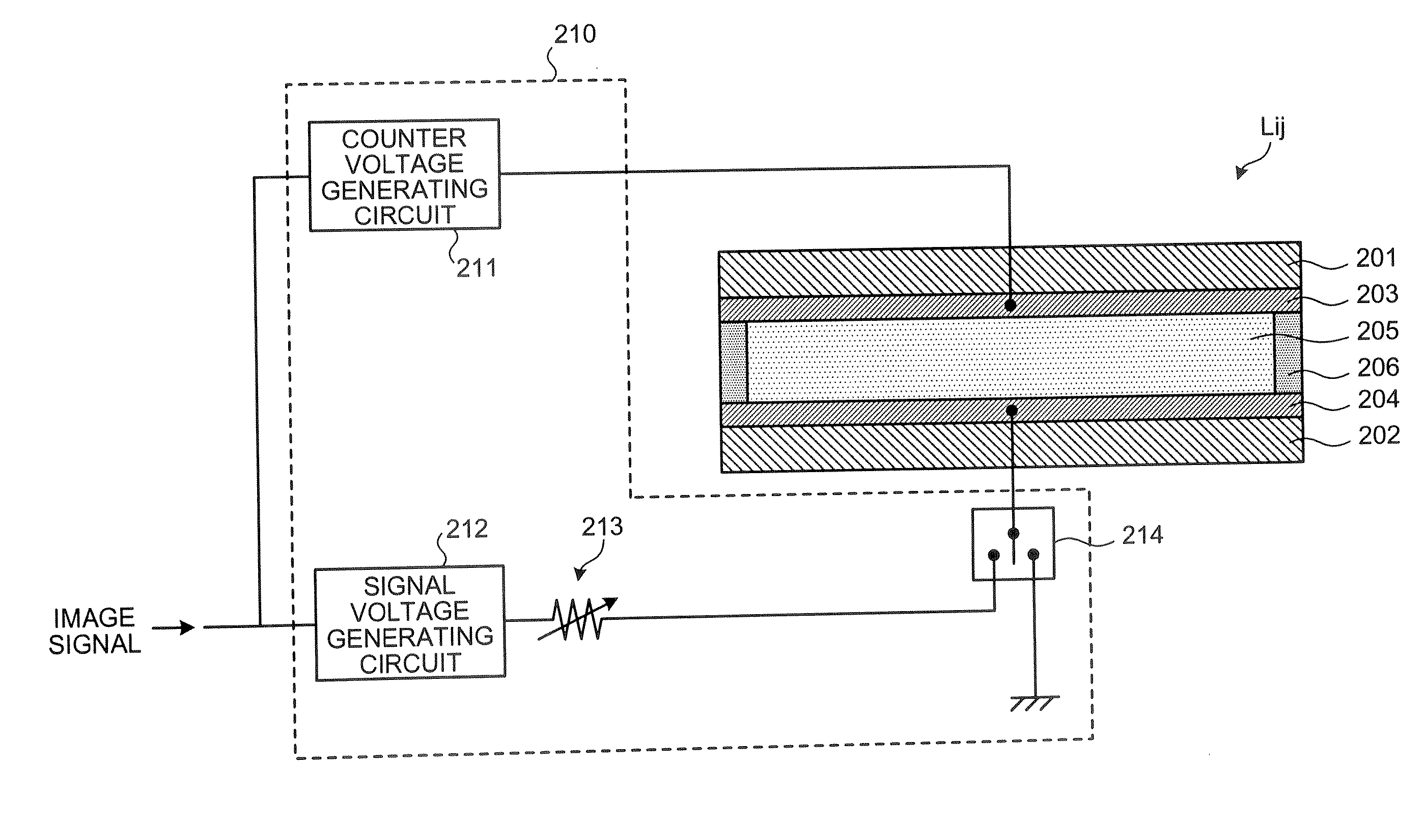
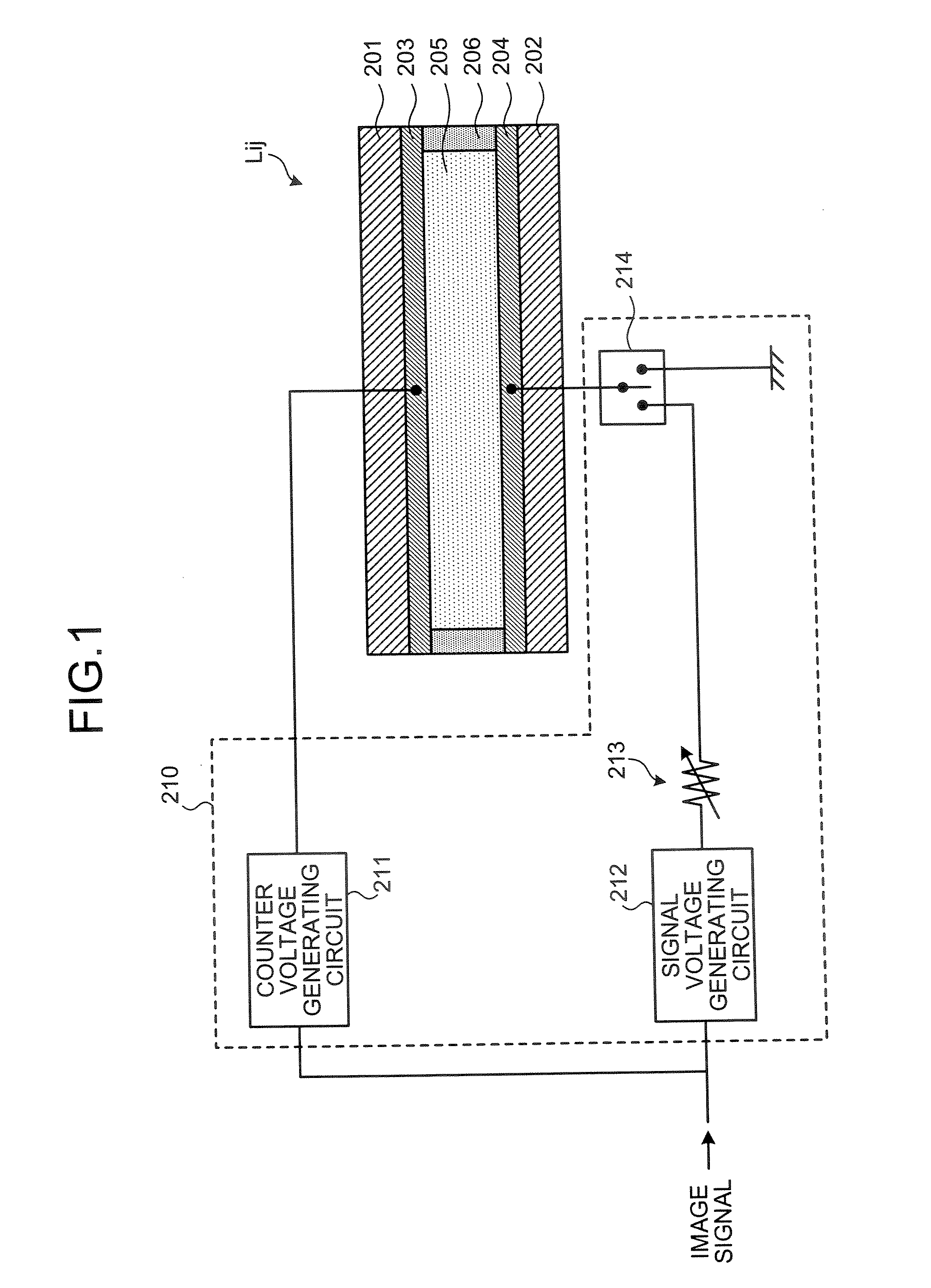
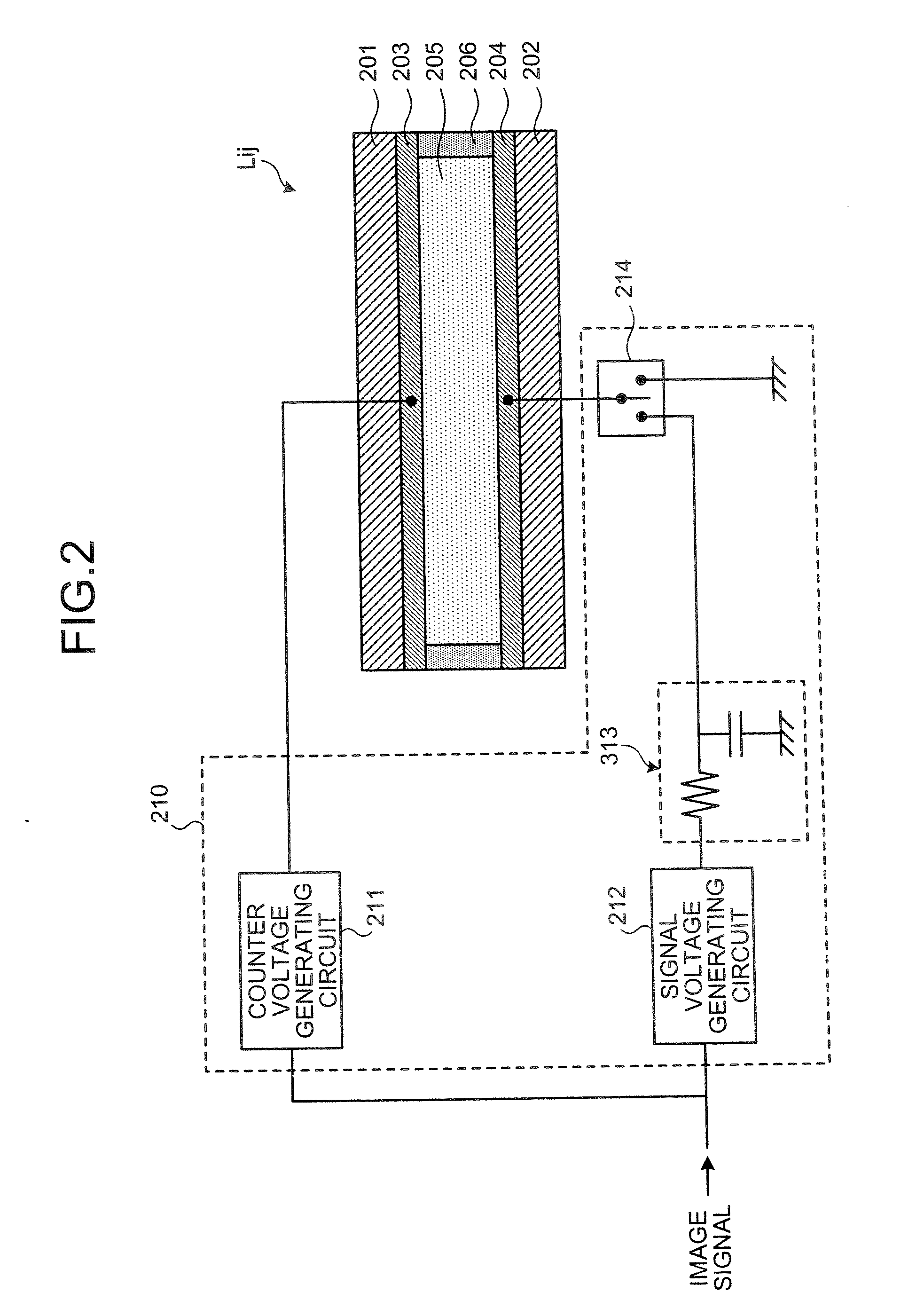
[0066]FIG. 7 is an explanatory diagram showing comparison of the light emitting state of the display element Li,j between the display apparatus in the first embodiment and the conventional display apparatus. In FIG. 7, the axis of abscissas represents the time, and the axis of ordinates represents the luminance of the display element. In FIG. 7, a curve 601 shows the light emitting state (a change in the luminance) of the display element Li,j in this embodiment, and a curve 602 shows the light emitting state (a change in the luminance) of the display element Li,j in the conventional display apparatus. As is clear from FIG. 7, in this embodiment (curve 601), when the voltage of the trapezoidal waveform is repeatedly applied to the display element, the light emission with high luminance by the display element can be maintained for a longer period of time in comparison with the case where the voltage of the rectangular waveform is applied like the conventional display apparatus (curve ...
second embodiment
[0074] A second embodiment is explained below.
[0075] The display apparatus in the first embodiment performs only the luminous display using the electrolyte solution layer of the display element, but the display apparatus in the second embodiment performs the luminous display using a first layer of the display element, and performs reflection display using a second layer of the display element.
[0076] In the display apparatus in this embodiment, the configuration of the display element Li,j of the pixel Xi,j is different from that in the first embodiment. FIG. 8 is a schematically sectional view showing one example of the configuration of the display element Li,j to be a display cell of the pixel Xi,j in the display apparatus according to the second embodiment, where i=1 to n, j=1 to m, and n and m are positive integers.
[0077] As shown in FIG. 8, each of the pixels Xi,j includes a first layer 806, a second layer 807, a first voltage applying unit (803, 804, VECL), a second voltage a...
third embodiment
[0110] A third embodiment is explained below.
[0111] In the display apparatus of the second embodiment, the two electrodes on the first substrate side are provided onto the first substrate 801, but in the display apparatus according to the third embodiment, a single electrode on the first substrate side is provided onto the first substrate 801 as shown in FIG. 12.
[0112]FIG. 12 is a sectional view schematically showing a configuration of the display element Li,j to be the display cell in the display apparatus according to the third embodiment. Only a part of the display apparatus in the third embodiment which is different from the second embodiment is explained, and the like parts are designated by like reference numerals, and their explanation is not repeated.
[0113] The reflection / luminous display realized by the display element Li,j in the first embodiment can be switched by a difference in an effective voltage (electric potential) and a reaction speed necessary for the ECL reacti...
PUM
 Abstract
Description
Claims
Application Information
 - R&D
- Intellectual Property
- Life Sciences
- Materials
- Tech Scout
- Unparalleled Data Quality
- Higher Quality Content
- 60% Fewer Hallucinations
Browse by: Latest US Patents, China's latest patents, Technical Efficacy Thesaurus, Application Domain, Technology Topic, Popular Technical Reports.
© 2025 PatSnap. All rights reserved.Legal|Privacy policy|Modern Slavery Act Transparency Statement|Sitemap|About US| Contact US: help@patsnap.com


