Plasma display apparatus and driving method thereof

Inactive Publication Date: 2007-05-17
PANASONIC CORP
View PDF10 Cites 3 Cited by
  • Summary
  • Abstract
  • Description
  • Claims
  • Application Information

AI Technical Summary

Benefits of technology

[0006] An object of the present invention is to provide a plasma display apparatus capable of sufficiently reducing crosstalk and sufficiently depressing a black luminance in the absence of signals, and a method for driving such a plasma display apparatus.

Problems solved by technology

Error discharges occur between the scan electrodes and the sustain electrodes of the adjacent discharge cells by these strong discharges, whereby crosstalk occurs between adjacent lines to deteriorate the quality of the display image.
Further, since the light emissions by the strong write discharges becomes unnecessary lights, a black luminance in the absence of signals cannot be sufficiently depressed, thereby deteriorating the quality of the display image.

Method used


Image

  • Plasma display apparatus and driving method thereof
  • Plasma display apparatus and driving method thereof
  • Plasma display apparatus and driving method thereof

Examples


first embodiment

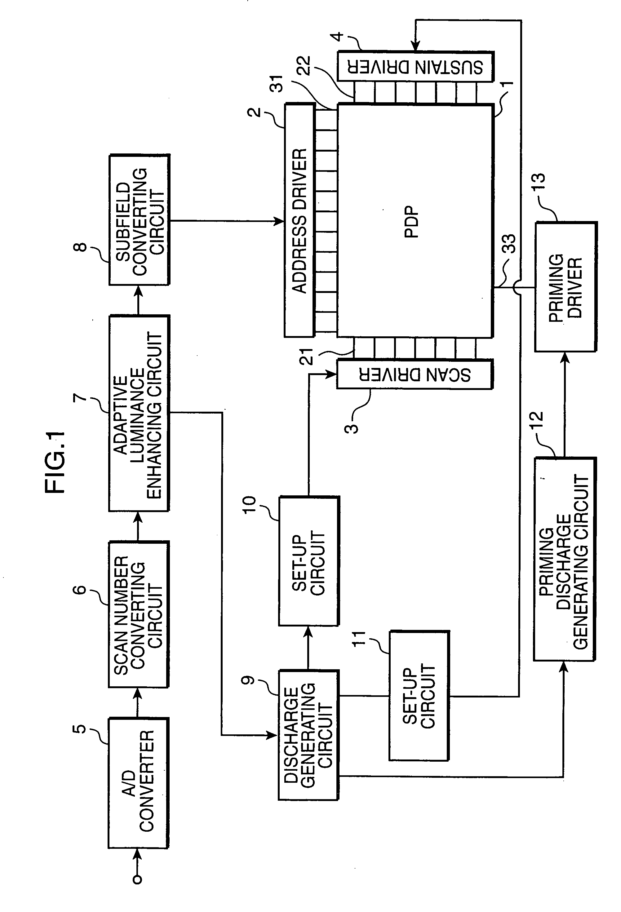
[0050] Hereinafter, a plasma display apparatus according to the present invention is described. FIG. 1 is a block diagram showing a construction of a plasma display apparatus according to the invention.

[0051] The plasma display apparatus of FIG. 1 is provided with a plasma display panel (hereinafter, “PDP”) 1, an address driver 2, a scan driver 3, a sustain driver 4, an A / D converter (analog-to-digital converter) 5, a scanning number converting circuit 6, an adaptive luminance enhancing circuit 7, a subfield converting circuit 8, a discharge generating circuit 9, set-up circuits 10, 11, a priming discharge generating circuit 12 and a priming driver 13.

[0052] A video signal VD is inputted to the A / D converter 5. Although not shown, horizontal synchronizing signals H and vertical synchronizing signals V are given to the A / D converter 5, the scanning number converting circuit 6, the adaptive luminance enhancing circuit 7, the subfield converting circuit 8, the discharge generating cir...

second embodiment

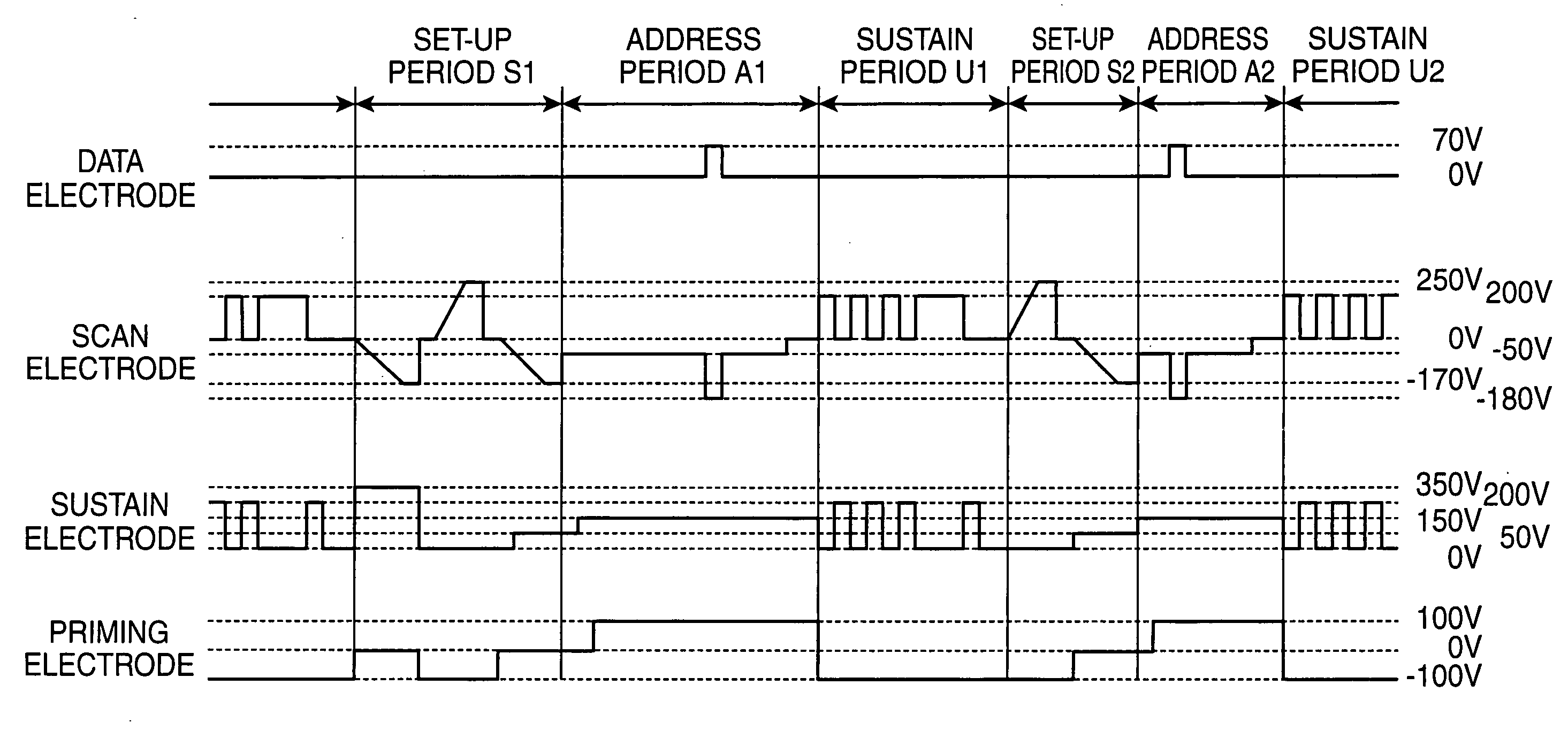
[0105] As shown in FIG. 12, similar to the second embodiment, during the set-up period S1 of the first subfield, the sustain driver 4 applies set-up pulses V1 of 350V for vertical synchronization to the sustain electrodes 22 when the plasma display apparatus is turned on, and thereafter applies set-up pulses V2 of 200V for vertical synchronization to the sustain electrodes 22.

[0106] Further, similar to the third embodiment, during the sustain period U1, the priming driver 13 reduces the voltages of the priming electrodes 33 from 100V to −100V when the last sustain pulses to the scan electrodes 21 rise, whereby discharges are generated between the scan electrodes 21 and the priming electrodes 33 to accumulate positive charges in the priming electrodes 33. Accordingly, in this embodiment, the effects of the second and third embodiments can be obtained in addition to those of the first embodiment.

[0107] Next, a plasma display apparatus according to a fifth embodiment of the present in...

third embodiment

[0126] As shown in FIG. 17, the priming driver 13 keeps the voltages of the priming electrodes 33 at 0V during the set-up periods S1, S2; increases them from 0V to 100V and keeps them at 100V during the address periods A1, A2; and reduces them from 100V to 0V when the first sustain pulses to the scan electrodes 21 rise and keeps them at 0V during the sustain periods U1, U2 similar to the At this moment, discharges are generated between the scan electrodes 21 and the priming electrodes 33 to accumulate positive charges in the priming electrodes 33.

[0127] As described above, since the voltages applied to the priming electrodes 33 take two values of 0V and 100V according to this embodiment, effects of being able to simplify the construction of the priming driver 13 and to reduce the power consumption and electromagnetic wave interference can be obtained in addition to those of the first and third embodiments.

[0128] Next, a plasma display apparatus according to a tenth embodiment of t...


PUM


Abstract

During each set-up period, wall charges of scan electrodes and sustain electrodes, between which sustain discharges were generated in the previous subfield, are adjusted, and parts toward the sustain electrodes of positive charges in the scan electrodes are replaced by negative charges and parts toward the scan electrodes of negative charges in the sustain electrodes are replaced by positive charges. During each address period, write pulses are applied to the scan electrodes to generate write discharges utilizing priming discharges between the scan electrodes and priming electrodes. During each sustain period, positive charges are accumulated in the entire surfaces of the scan electrodes and negative charges are accumulated in the entire surfaces of the sustain electrodes.

Description

TECHNICAL FIELD [0001] The present invention relates to a plasma display apparatus for displaying images in gradation by dividing one field into a plurality of subfields, and a driving method for such a plasma display apparatus. BACKGROUND TECHNOLOGY [0002] Plasma display apparatuses have advantages of being able to be thinned and to have larger screens. An AC plasma display panel used in such a plasma display apparatus is such that a front plate made of a glass substrate and formed by arraying a plurality of rows of scan electrodes and sustain electrodes for carrying out surface discharges, and a back plate on which data electrodes are arrayed in a plurality of rows are so combined that the scan electrodes and the sustain electrodes are orthogonal to the data electrodes, thereby forming matrix-shaped discharge cells, as disclosed, for example, in Japanese Unexamined Patent Publication No. 2001-195990. [0003] A subfield method for displaying a halftone by temporally overlapping a pl...

Claims


Application Information

Patent Timeline
IPC IPC(8): G09G3/28G09G3/292G09G3/20G09G3/291G09G3/293G09G3/294G09G3/296G09G3/298H01J11/12H01J11/22H01J11/24H01J11/26H01J11/28H01J11/34
CPCG09G3/2927G09G3/293G09G3/2986G09G2320/0209G09G2320/0228G09G2320/0238G09G3/294G09G3/296
Inventor WAKABAYASHI, TOSHIKAZUTACHIBANA, HIROYUKIKOSUGI, NAOKIMURAI, RYUICHIOGAWA, KENJIHORIE, YOSHIMASA
Owner PANASONIC CORP
Why Eureka
Try Eureka