Liquid crystal display device comprising a first optical compensating member disposed without a birefringent medium sandwiched between the liquid crystal layer and the first optical compensating member

a liquid crystal display and optical compensating member technology, applied in non-linear optics, instruments, optics, etc., can solve the problems of inability to reduce black luminance in sufficient proportion, inability and color disturbance in oblique direction, so as to reduce black luminance and color deterioration, the effect of lessening impacts

Active Publication Date: 2011-12-13
JAPAN DISPLAY INC +1
View PDF24 Cites 0 Cited by
  • Summary
  • Abstract
  • Description
  • Claims
  • Application Information

AI Technical Summary

Benefits of technology

[0021]The IPS mode employs homogeneously aligned liquid-crystal molecules and two polarizers arranged so that the absorption axis of one polarizer pointing in a vertical direction with respect to the front of a screen and the absorption axis of the other polarizer pointing in a horizontal direction are orthogonalized. When the screen is viewed obliquely from the vertical and horizontal directions, the absorption axes of the two polarizers take a positional relationship in which the absorption axes are orthogonal to each other. Black luminance can, therefore, be sufficiently reduced since the homogeneously aligned liquid-crystal molecules and the absorption axis of one polarizer are parallel. In contrast to this, when the screen is viewed obliquely from a 45° azimuthal direction, since the angle formed between the absorption axes of the two polarizers shifts from 90°, transmitted light causes birefringence and this, in turn, causes leakage light, thus making sufficient reduction of black luminance impossible. Additionally, the amount of oblique leakage light differs according to wavelength and this difference causes a color disturbance. Accordingly, an object of the present invention is to provide means which, in order to obtain appropriate display characteristics at practically every omni-directional angle during black display in the IPS mode, reduces both an increase in luminance of the black display made when a screen is viewed from an oblique direction, and the color disturbance.
[0024]In the liquid crystal display device of the present invention, it is possible, by including polarizers, a liquid-crystal layer, and an optical compensating member, in the device configuration, and defining respective optical constants of each of these optical members, to lessen impacts of the liquid-crystal layer and optical compensating member under an oblique field and to reduce black luminance and color deterioration in an oblique direction.

Problems solved by technology

The problem to be solved is that a liquid crystal display device of an in-plane switching (IPS) mode that has liquid-crystal molecules homogeneously aligned during black display and controls transmission and cutoff of light by applying a horizontal electric field to the liquid-crystal molecules suffers a luminance disturbance and color disturbance in an oblique direction.
In contrast to this, when the screen is viewed obliquely from a 45° azimuthal direction, since the angle formed between the absorption axes of the two polarizers shifts from 90°, transmitted light causes birefringence and this, in turn, causes leakage light, thus making sufficient reduction of black luminance impossible.
Additionally, the amount of oblique leakage light differs according to wavelength and this difference causes a color disturbance.

Method used


Image

  • Liquid crystal display device comprising a first optical compensating member disposed without a birefringent medium sandwiched between the liquid crystal layer and the first optical compensating member
  • Liquid crystal display device comprising a first optical compensating member disposed without a birefringent medium sandwiched between the liquid crystal layer and the first optical compensating member
  • Liquid crystal display device comprising a first optical compensating member disposed without a birefringent medium sandwiched between the liquid crystal layer and the first optical compensating member

Examples


embodiments

[0090]Content of the present invention is described in further detail below by showing more specific examples of the invention. The embodiments below represent specific examples of the present invention and do not limit the invention. Study results derived from numeric calculations obtained using optical simulation based on the 4×4-matrix method disclosed in Non-Patent Document 3 are included in the embodiments. The simulation assumes a general configuration and is based on spectral characteristics of a tri-wavelength cathode-ray tube used in a normal type of backlight, spectral transmission characteristics of a red / green / blue tri-color filter, and polarizing layer spectral characteristics of the 1224DU polarizer manufactured by the Nitto Denko Corp. The above simulation also assumes a nematic liquid crystal having a liquid-crystal layer, which contains liquid-crystal molecules whose extraordinary-light refractive index is 1.573 and whose ordinary-light refractive index is 1.484, an...

first embodiment

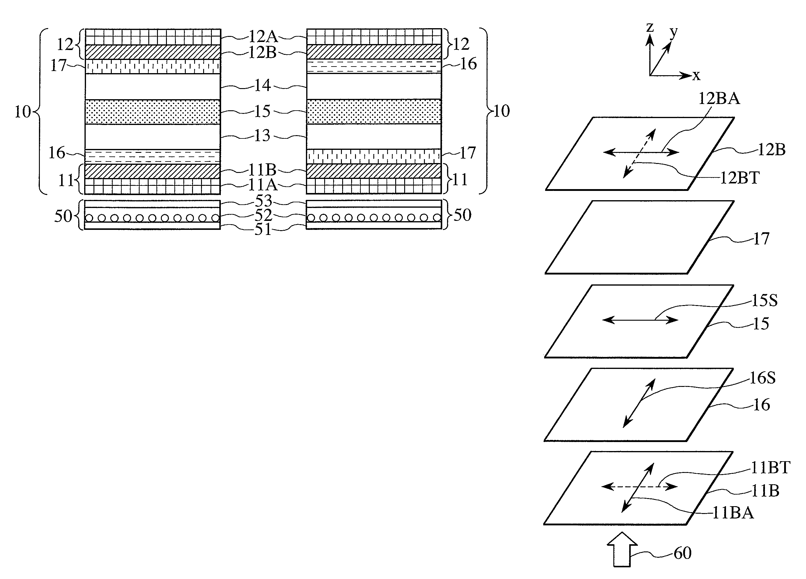
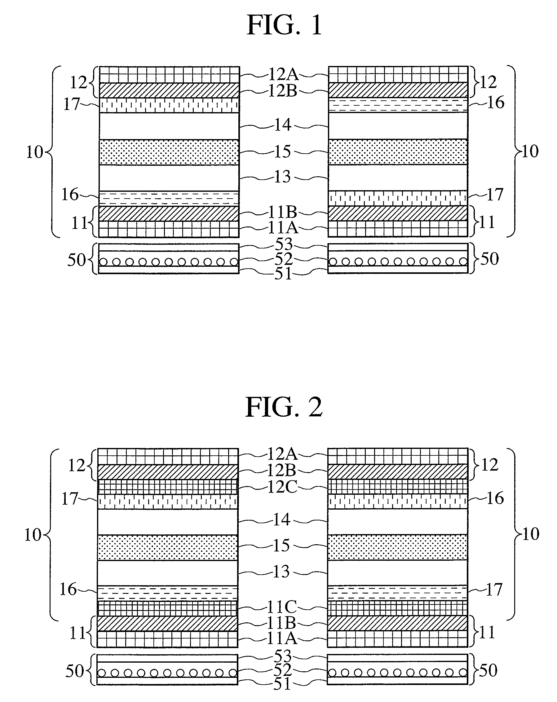
[0100]A structure of a first embodiment is shown in the left of FIG. 1, and an optical configuration of the e-mode, in FIG. 5. In the present embodiment, a negative “a-plate” is used as an optical compensating member 16, and a biaxially anisotropic optical compensating member with an Nz coefficient smaller than 0 is used as an optical compensating member 17. This configuration makes it possible to achieve the polarization state changes shown in FIGS. 12A and 12B. A polarization state of light which has passed through a transmission axis 11BT of a polarizing layer 11B is denoted by 200T and undergoes a change 416 to be changed into a polarization state 516 by the optical compensating member 16. Next, the polarization state undergoes a change 415 to be changed into a polarization state 515 by a liquid-crystal layer 15 as if a history of the change 416 by the optical compensating member 16 were traced back. The polarization state further undergoes a change 417 into a polarization state...

second embodiment

[0107]A structure of a second embodiment is shown in the right of FIG. 1, and an optical configuration of the o-mode, in FIG. 6. In the present embodiment, a negative “a-plate” is used as an optical compensating member 16, and a biaxially anisotropic optical compensating member with an Nz coefficient smaller than 0 is used as an optical compensating member 17. This configuration makes it possible to achieve the polarization state changes shown in FIGS. 13A and 13B. A polarization state of light which has passed through a transmission axis 11BT of a polarizing layer 11B is denoted by 200T and undergoes a change 417 to be changed into a polarization state 517 by the optical compensating member 17. Next, the polarization state undergoes a change 415 to be changed into a polarization state 515 by a liquid-crystal layer 15. The polarization state further undergoes a change 416 into a point of a polarization state 201A by the optical compensating member 16 as if a history of the change 41...


PUM

PropertyMeasurementUnit
thicknessaaaaaaaaaa
azimuthal angleaaaaaaaaaa

Abstract

A liquid crystal display device comprising a first optical compensating member disposed without a birefringent medium sandwiched between a liquid-crystal layer and the first optical compensating member. The first optical compensating member is constructed so that when a refractive index thereof in a slow-axis direction in a plane parallel to the substrate is taken as n1, a refractive index in a fast-axis direction in the plane parallel to the substrate is taken as n2, and a refractive index in a thickness direction is taken as n3, the first optical compensating member satisfies n1˜n3>n2 and a slow axis thereof in the plane parallel to the substrate is substantially vertical to an optical axis of the liquid-crystal layer.

Description

BACKGROUND OF THE INVENTION[0001]1. Field of the Invention[0002]The present invention relates to a liquid crystal display device having a liquid-crystal layer sandwiched between one pair of substrates.[0003]2. Description of the Related Art[0004]In Patent Documents 1, 2, and 3 listed below, a scheme with comb-like electrodes provided on one substrate is proposed as a scheme in which an electric field is applied to a liquid crystal on the substrate horizontally. This scheme is hereinafter referred to as the horizontal field scheme or in-plane switching (IPS) mode. In this scheme, the liquid-crystal molecules rotate in a parallel plane with respect primarily to the substrate. It is known, therefore, that a wide viewing angle can be obtained since, when the crystal is viewed obliquely, the difference in birefringent index between the application of the electric field and non-application thereof is insignificant.[0005]At the same time, it is also seen that in the IPS mode, although chan...

Claims


Application Information

Patent Timeline
Patent Type & Authority Patents(United States)
IPC IPC(8): G02F1/1335
CPCG02F1/13363G02F1/134363G02F2001/133565G02F2001/133637G02F2202/40G02F2413/02G02F2413/12G02F2413/14G02F1/133565G02F1/133637
Inventor OJIMA, KENTAROKAJITA, DAISUKEHIYAMA, IKUOISHII, MASAHIRO
Owner JAPAN DISPLAY INC
Why Eureka
Try Eureka