Liquid crystal display device
a liquid crystal display and display device technology, applied in non-linear optics, instruments, optics, etc., can solve the problems of insufficient reduction of black luminance, inability and disturbance of luminance and color in oblique directions, so as to reduce black luminance and color deterioration, the effect of lessening impacts
- Summary
- Abstract
- Description
- Claims
- Application Information
AI Technical Summary
Benefits of technology
Problems solved by technology
Method used
Image
Examples
embodiments
[0090]Content of the present invention is described in further detail below by showing more specific examples of the invention. The embodiments below represent specific examples of the present invention and do not limit the invention. Study results derived from numeric calculations obtained using optical simulation based on the 4×4-matrix method disclosed in Non-Patent Document 3 are included in the embodiments. The simulation assumes a general configuration and is based on spectral characteristics of a tri-wavelength cathode-ray tube used in a normal type of backlight, spectral transmission characteristics of a red / green / blue tri-color filter, and polarizing layer spectral characteristics of the 1224DU polarizer manufactured by the Nitto Denko Corp. The above simulation also assumes a nematic liquid crystal having a liquid-crystal layer, which contains liquid-crystal molecules whose extraordinary-light refractive index is 1.573 and whose ordinary-light refractive index is 1.484, an...
first embodiment
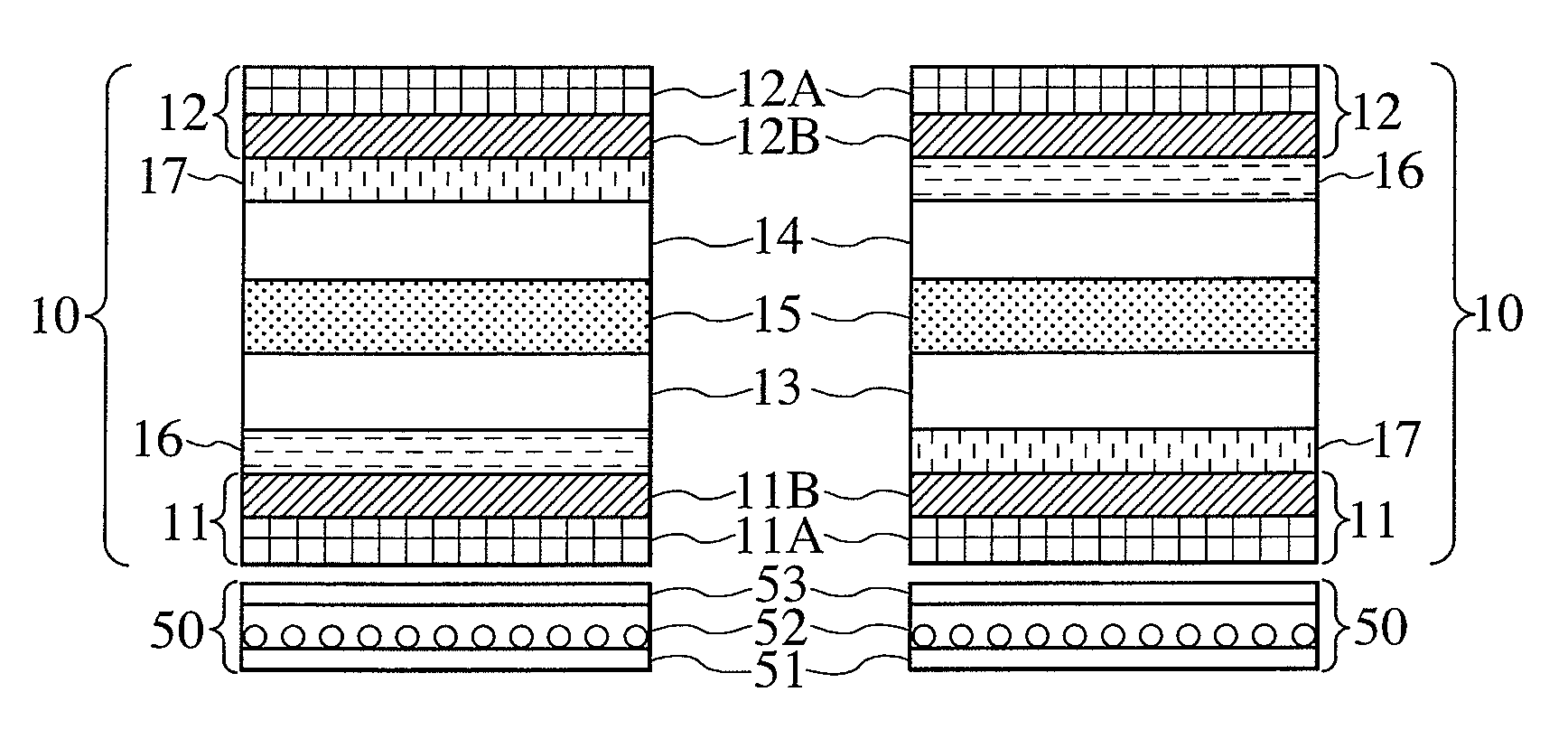
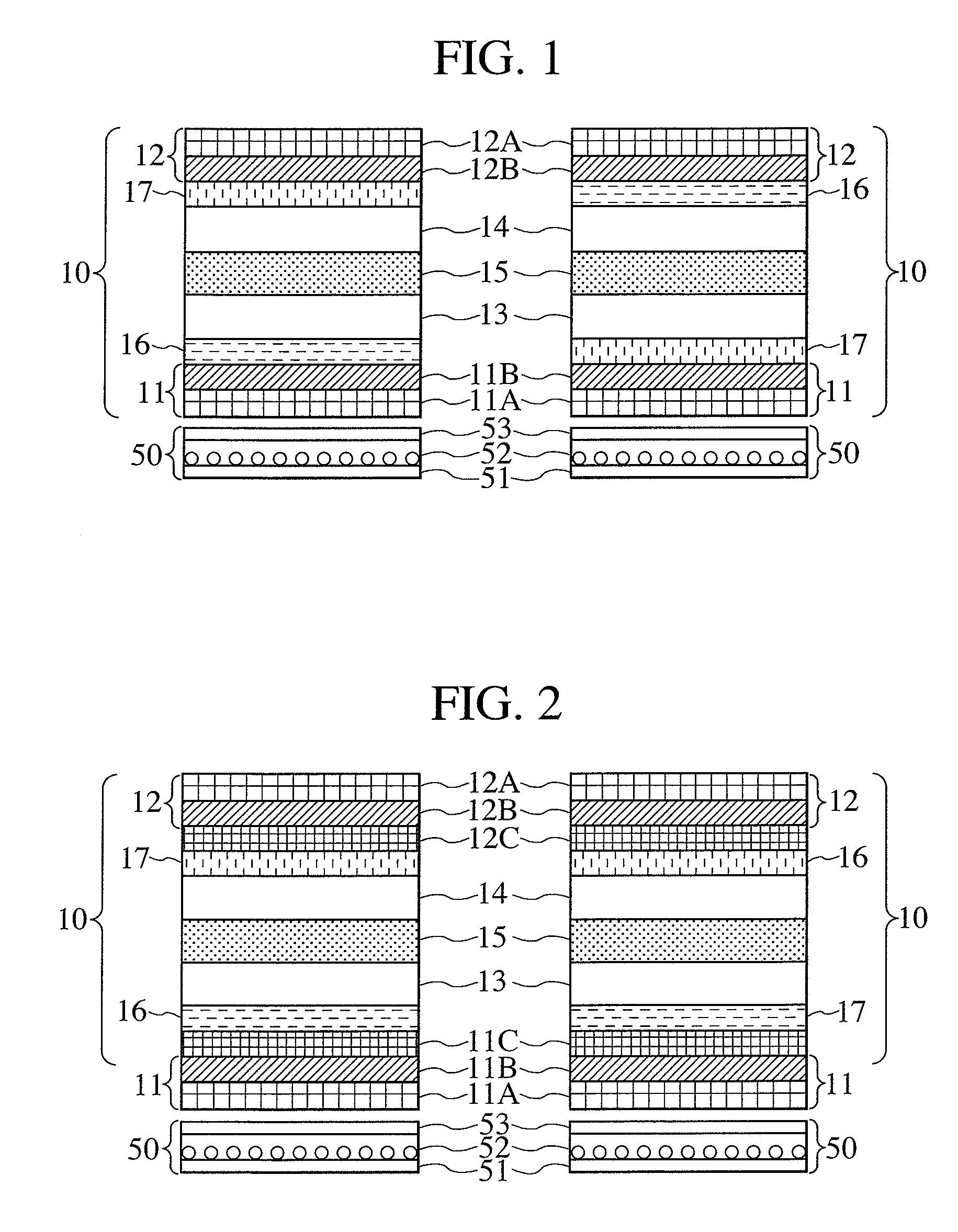
[0104]A structure of a first embodiment is shown in the left of FIG. 1, and an optical configuration of the e-mode, in FIG. 5. In the present embodiment, a negative “a-plate” is used as an optical compensating member 16, and a biaxially anisotropic optical compensating member with an Nz coefficient smaller than 0 is used as an optical compensating member 17. This configuration makes it possible to achieve the polarization state changes shown in FIGS. 12A and 12B. A polarization state of light which has passed through a transmission axis 11BT of a polarizing layer 11B is denoted by 200T and undergoes a change 416 to be changed into a polarization state 516 by the optical compensating member 16. Next, the polarization state undergoes a change 415 to be changed into a polarization state 515 by a liquid-crystal layer 15 as if a history of the change 416 by the optical compensating member 16 were traced back. The polarization state further undergoes a change 417 into a polarization state...
second embodiment
[0111]A structure of a second embodiment is shown in the right of FIG. 1, and an optical configuration of the o-mode, in FIG. 6. In the present embodiment, a negative “a-plate” is used as an optical compensating member 16, and a biaxially anisotropic optical compensating member with an Nz coefficient smaller than 0 is used as an optical compensating member 17. This configuration makes it possible to achieve the polarization state changes shown in FIGS. 13A and 13B. A polarization state of light which has passed through a transmission axis 11BT of a polarizing layer 11B is denoted by 200T and undergoes a change 417 to be changed into a polarization state 517 by the optical compensating member 17. Next, the polarization state undergoes a change 415 to be changed into a polarization state 515 by a liquid-crystal layer 15. The polarization state further undergoes a change 416 into a point of a polarization state 201A by the optical compensating member 16 as if a history of the change 41...
PUM
| Property | Measurement | Unit |
|---|---|---|
| thickness | aaaaa | aaaaa |
| birefringent | aaaaa | aaaaa |
| refractive index | aaaaa | aaaaa |
Abstract
Description
Claims
Application Information
 - R&D
- Intellectual Property
- Life Sciences
- Materials
- Tech Scout
- Unparalleled Data Quality
- Higher Quality Content
- 60% Fewer Hallucinations
Browse by: Latest US Patents, China's latest patents, Technical Efficacy Thesaurus, Application Domain, Technology Topic, Popular Technical Reports.
© 2025 PatSnap. All rights reserved.Legal|Privacy policy|Modern Slavery Act Transparency Statement|Sitemap|About US| Contact US: help@patsnap.com


