Inkjet recording apparatus

Active Publication Date: 2007-05-17
MIYAKOSHI PRINTING MACHINERY
View PDF1 Cites 31 Cited by
  • Summary
  • Abstract
  • Description
  • Claims
  • Application Information

AI Technical Summary

Benefits of technology

[0018] According to this specific makeup, it becomes possible to blow air in a laminar flow from the upstream side into below the upstream-most of a series of the inkjet heads

Problems solved by technology

And, they become an ink mist, and the problem arises that the ink mist floating between the nozzle head and recording paper comes to contaminate not only the surface of recording paper but also the nozzle head.
Since the nozzle head is provided with the suction port in the former of the prior art and the suction and blast ports in the latter of the prior art, an air piping which connects to such a p

Method used


Image

  • Inkjet recording apparatus
  • Inkjet recording apparatus
  • Inkjet recording apparatus

Examples


Embodiment Construction

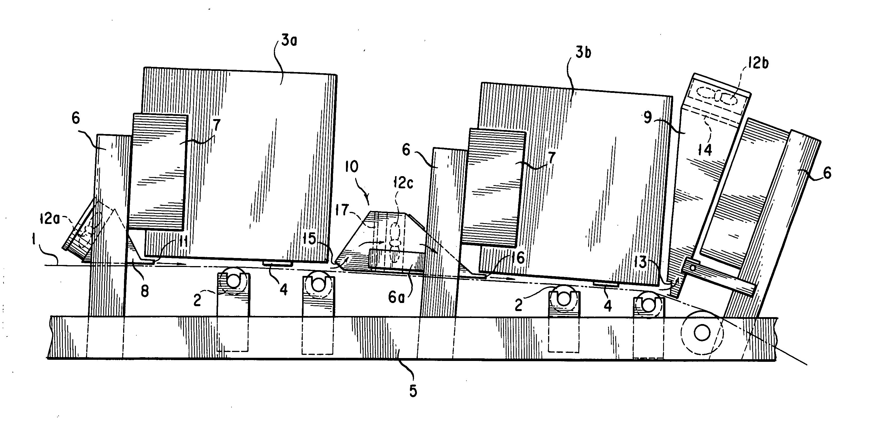
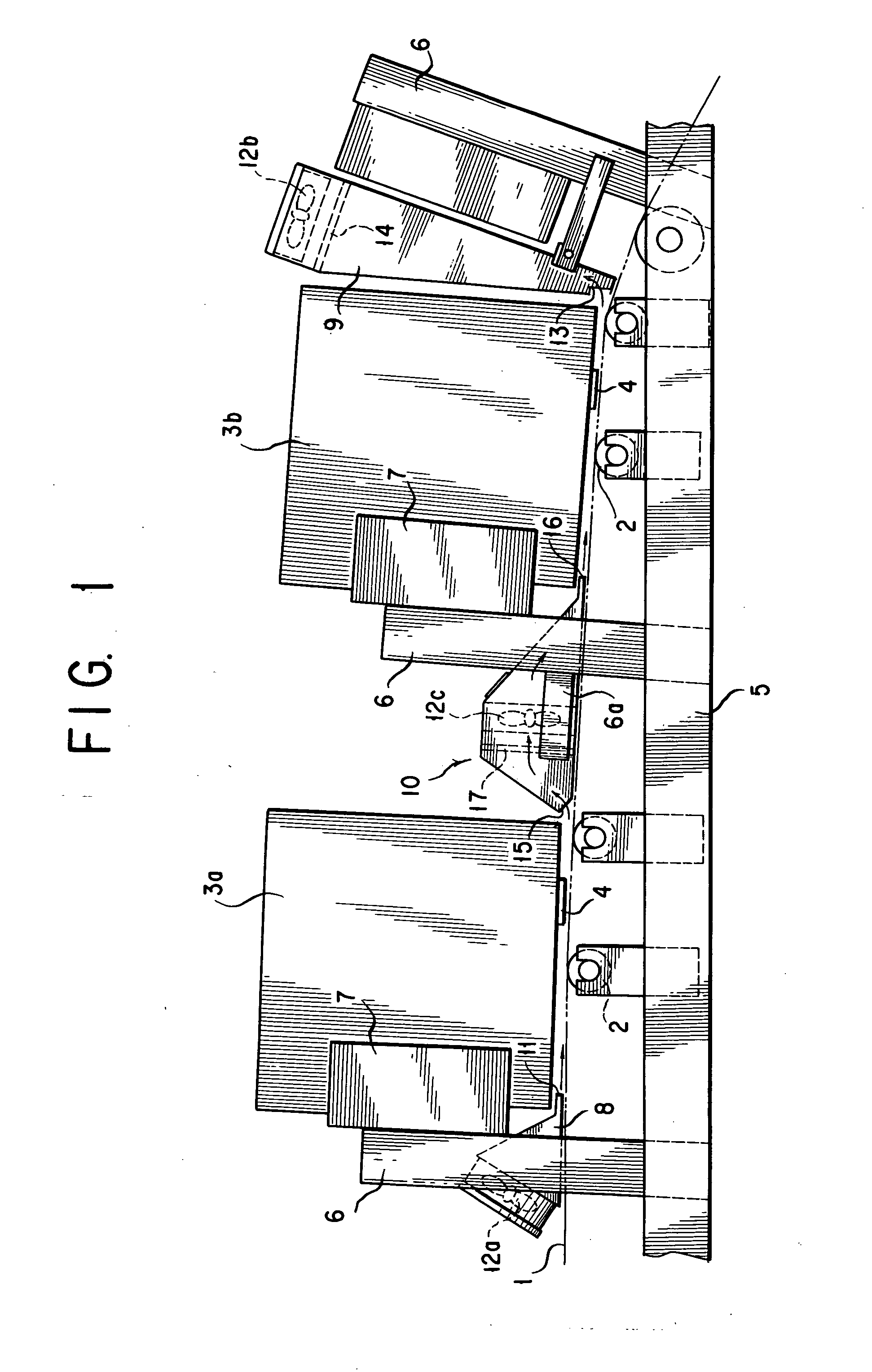
[0025] An explanation is given of forms of implementation of the present invention with reference to the Drawing Figures. In FIG. 1, the apparatus includes guide rollers 2, 2, . . . , constituting a paper conveyance line along which recording paper (i. e., roll paper or sheet paper) is to travel, a plurality of, here two, inkjet heads, 3a and 3b, mounted along this paper conveyance line, and nozzle heads 4, 4 each of which is mounted at an under surface of the inkjet head 3a, 3b. Each of these nozzle heads 4 and 4 has a structure that ink nozzles are arranged therein in a line in a direction of the width of recording paper 1.

[0026] Each of the inkjet heads 3a and 3b is supported via a supporting unit 7 from a bracket 6 fastened to a frame 5. The supporting unit 7 is equipped with known adjustment mechanisms including a height adjusting mechanism for adjusting the spacing (height) of the nozzle head 4 of the inkjet head 3a, 3b from the recording paper 1 traveling on the aforemention...


PUM


Abstract

An inkjet recording apparatus having a plurality of inkjet heads arranged along a paper conveyance line is disclosed, which is capable of collecting an ink mist efficiently without making the inkjet heads intricate in makeup. To this end, an air suction and blast unit is disposed in a space between the upstream and downstream inkjet heads which are successive and includes a housing, an air suction port provided at one side of the housing, an air blast nozzle provided at the other side of the housing, a fan provided between the air suction port and the air blast nozzle in the housing for creating an air flow flowing from the air suction port to the air blast nozzle and a mist filter in the housing for catching an ink mist in the air flow created by the fan, wherein the air suction port is opposed from a downstream side to a gap between an under surface of the upstream inkjet head and the paper conveyance line while the air blast nozzle is opposed from an upstream side to a gap between the downstream inkjet head and the paper conveyance line.

Description

BACKGROUND OF THE INVENTION [0001] 1. Technical Field [0002] The present invention relates to an inkjet recording apparatus n which a plurality of inkjet heads are arranged in a direction in which recording paper is to travel and, more particularly, to such an inkjet recording apparatus which is capable of collecting and removing an ink mist that occurs between an under surface of each inkjet head and the recording paper. [0003] 2. Description of the Prior Art [0004] In an inkjet recording apparatus, while recording is effected by the adhesion of ink particles discharged from a nozzle head to recording paper, during recording with such ink, ink particles may occur which are not adhered to the recording paper (recording medium). And, they become an ink mist, and the problem arises that the ink mist floating between the nozzle head and recording paper comes to contaminate not only the surface of recording paper but also the nozzle head. [0005] For this reason, each nozzle head in an i...

Claims


Application Information

Patent Timeline
IPC IPC(8): B41J2/165
CPCB41J2/1714B41J25/3088B41J2/2146B41J25/001
Inventor IZAWA, HIDEOSETOYAMA, JUNICHIYAMAZAKI, YUUICHI
Owner MIYAKOSHI PRINTING MACHINERY
Why Eureka
Try Eureka