Video image capture device

a technology of video image and capture device, which is applied in the field of video image capture device, can solve problems such as image quality suffers

Inactive Publication Date: 2007-05-17
OLYMPUS CORP
View PDF10 Cites 18 Cited by
  • Summary
  • Abstract
  • Description
  • Claims
  • Application Information

AI Technical Summary

Benefits of technology

[0010] In this video image capture device, first corrected image data, corresponding to the first angle of view of the original image data and output by the distortion correction circuit, may be stored in the recording device as image data corresponding to the first angle of view; and second corrected image data, corresponding to the second angle of view of the original image data and output by the di...

Problems solved by technology

Compared with the optical zoom, the electronic zoom requires no driving portions and is co...

Method used


Image

  • Video image capture device
  • Video image capture device
  • Video image capture device

Examples


first embodiment

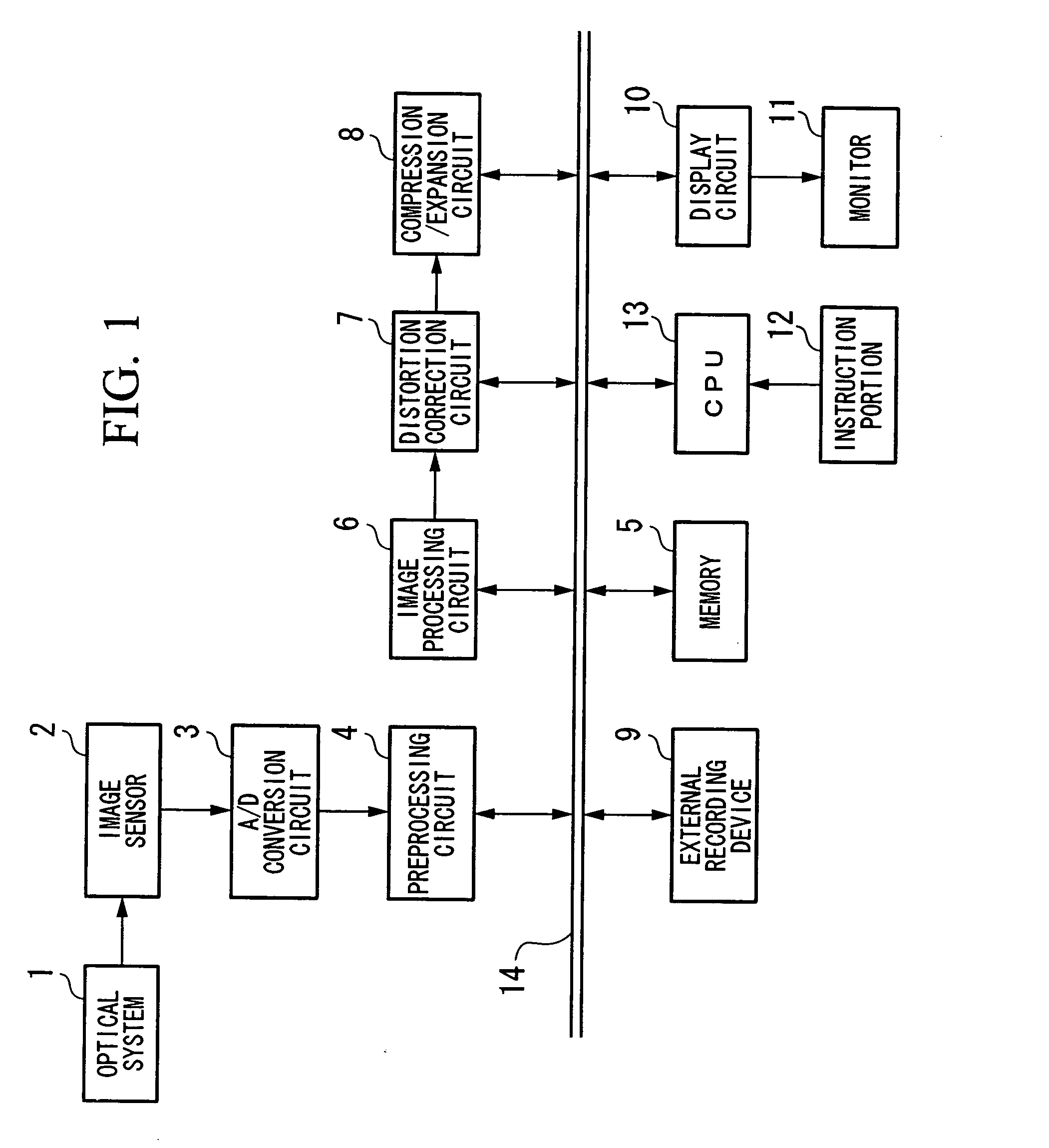
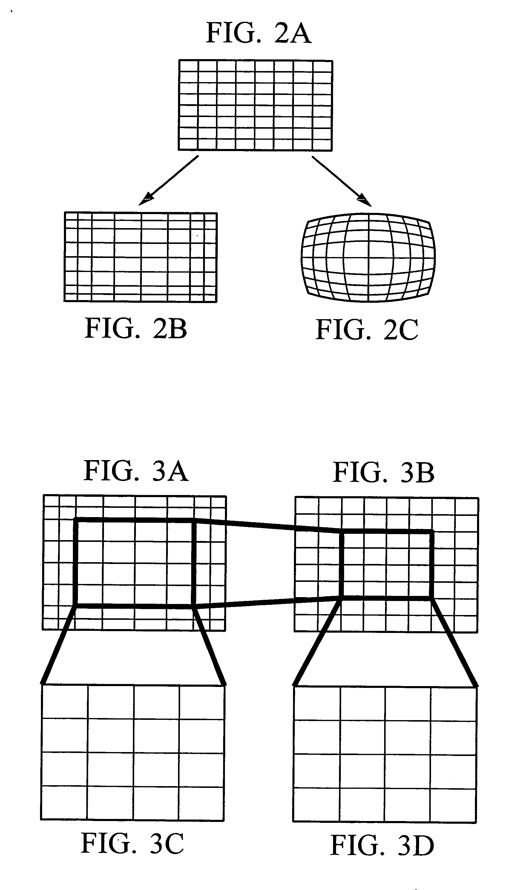
[0037]FIG. 1 is a block diagram showing the configuration of the video image capture device of a first embodiment of the invention. In FIG. 1, an optical system 1 has distortion such that the center portion is enlarged and the peripheral portion is reduced.

[0038] The subject image light condensed by the optical system 1 is focused at the light-receiving face of an image sensor 2. The image sensor 2 receives the optical image and converts this into electrical signals. As the image sensor 2, a CCD (Charge Coupled Device) image sensor or a CMOS (Complementary MOS) image sensor is used. An RGB filter is affixed in a Bayer arrangement to the light-receiving face of the image sensor 2. The output signals from the image sensor 2 are converted into digital signals by an A / D conversion circuit 3 and sent to a preprocessing circuit 4.

[0039] The preprocessing circuit 4 performs correction of pixel defects in the captured image signals input from the A / D conversion circuit 3, as well as OB su...

second embodiment

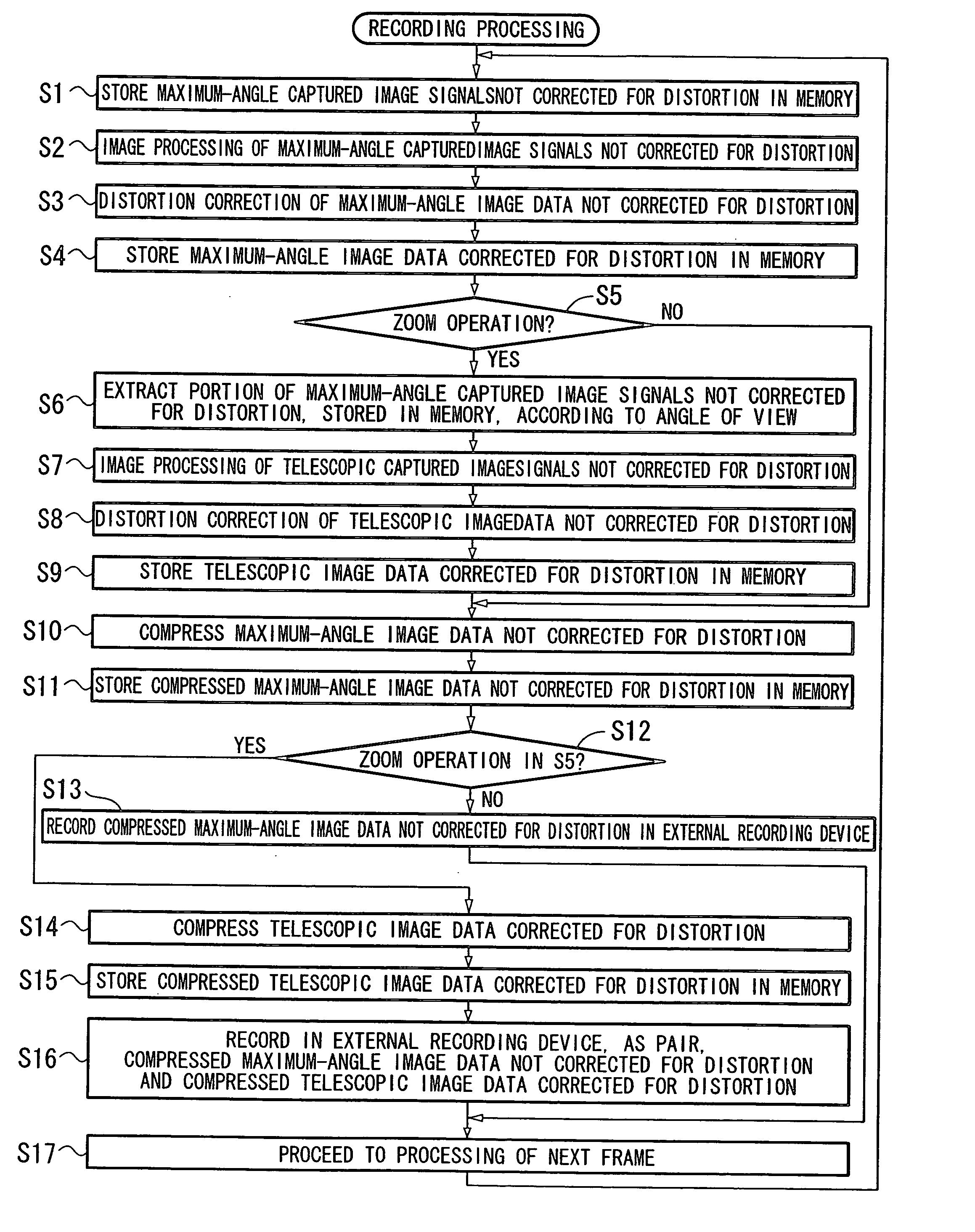
[0083] A second embodiment of the invention will be explained, referring to the drawings. The second embodiment differs from the first embodiment with respect to the maximum-angle image data recorded to the external recording device 9. That is, in the first embodiment, compressed maximum-angle image data corrected for distortion and compressed telescopic image data corrected for distortion were recorded to the external recording device 9 at the time of recording. In contrast, in this second embodiment, compressed maximum-angle image data not corrected for distortion and compressed telescopic image data corrected for distortion are recorded to the external recording device 9. The configuration of the video image capture device in the second embodiment of the invention is similar to that of the first embodiment, and an explanation is omitted.

[0084]FIG. 9 is a flowchart showing recording processing in the second embodiment of the invention. In FIG. 9, an optical image obtained via the...


PUM


Abstract

A video image capture device of the present invention includes: an optical system having distortion characteristics which enlarge the center portion and compress the peripheral portions; an image sensor which performs photoelectric conversion of a subject image focused by the optical system to output as original image data; a distortion correction circuit which corrects distortion in the original image data; an instruction portion which sets the size of an extraction angle of view for the original image data before correction of distortion; and a recording device which, taking the angle of view of the original image data to be a first angle of view, stores in succession image data corresponding to the first angle of view of the original image data and, as pairs, image data corresponding to a second angle of view narrower than the first angle of view set by the instruction portion.

Description

BACKGROUND OF THE INVENTION [0001] 1. Field of the Invention [0002] This invention relates to a video image capture device, and in particular relates to a video image capture device which performs zoom operations using an optical system having distortion characteristics. [0003] Priority is claimed on Japanese Patent Application No. 2005-328511, filed Nov. 14, 2005, the content of which is incorporated herein by reference. [0004] 2. Description of Related Art [0005] In image input devices such as camcorders, and digital cameras, zoom functions are widely used, in which the lens focal distance is modified so as to freely enlarge and reduce an image, corresponding to the distance to the subject for image capture and the size occupying the angle of view. Such zoom functions are broadly divided into optical zoom, which is ordinarily realized by mechanically moving an internal lens, and electronic zoom, in which a portion of the image data output from an image sensor is enlarged. Compared...

Claims


Application Information

Patent Timeline
IPC IPC(8): H04N7/00H04N5/225H04N5/228H04N5/232
CPCH04N5/2253H04N5/23296H04N5/2628H04N23/54H04N23/69
Inventor SEKIMOTO, TOMOMIUENO, AKIRA
Owner OLYMPUS CORP
Why Eureka
Try Eureka