
System and method for synchronizing a back-up device in a communications environment

Active Publication Date: 2007-05-17
CISCO TECH INC
View PDF15 Cites 15 Cited by
  • Summary
  • Abstract
  • Description
  • Claims
  • Application Information

AI Technical Summary

Benefits of technology

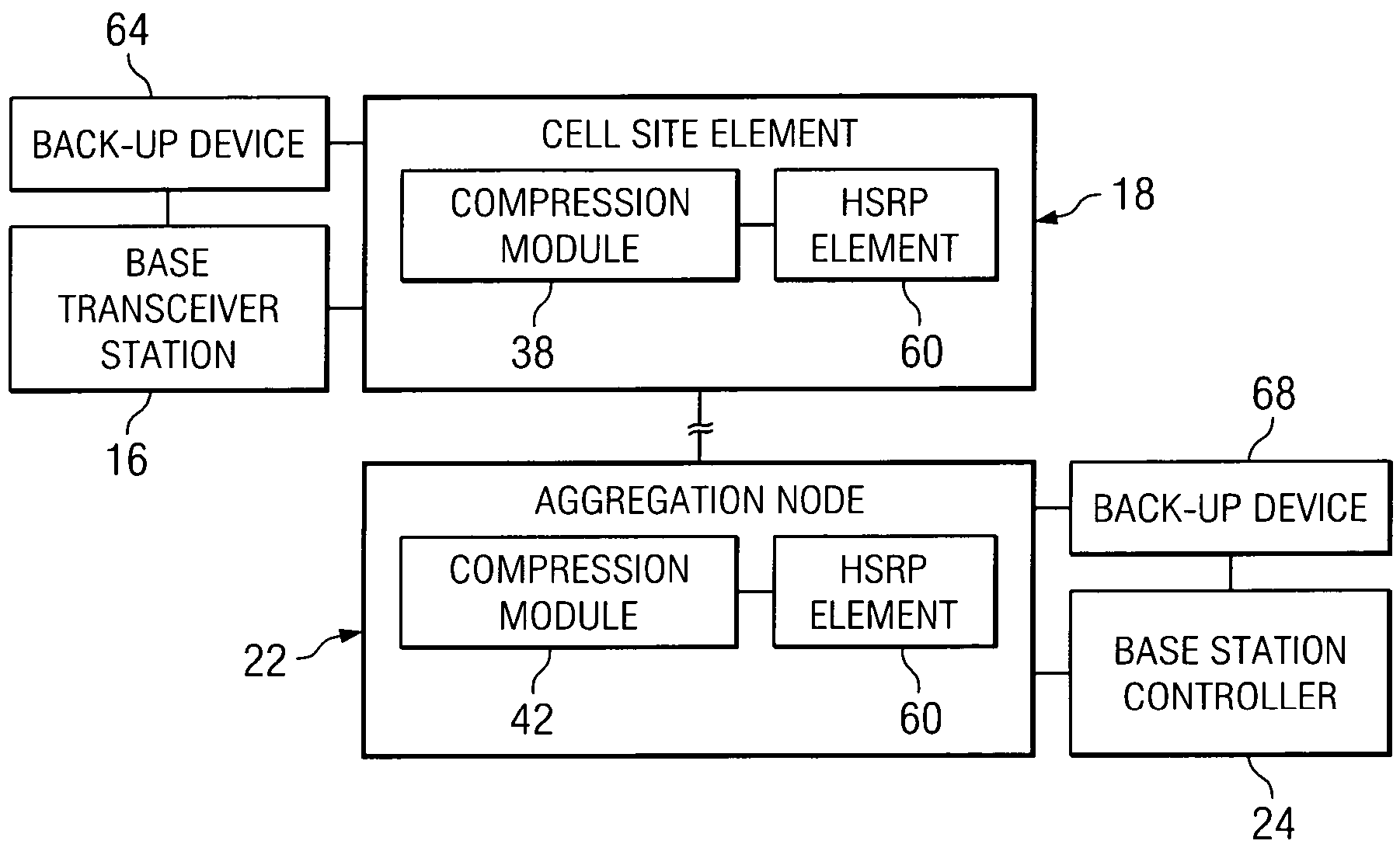
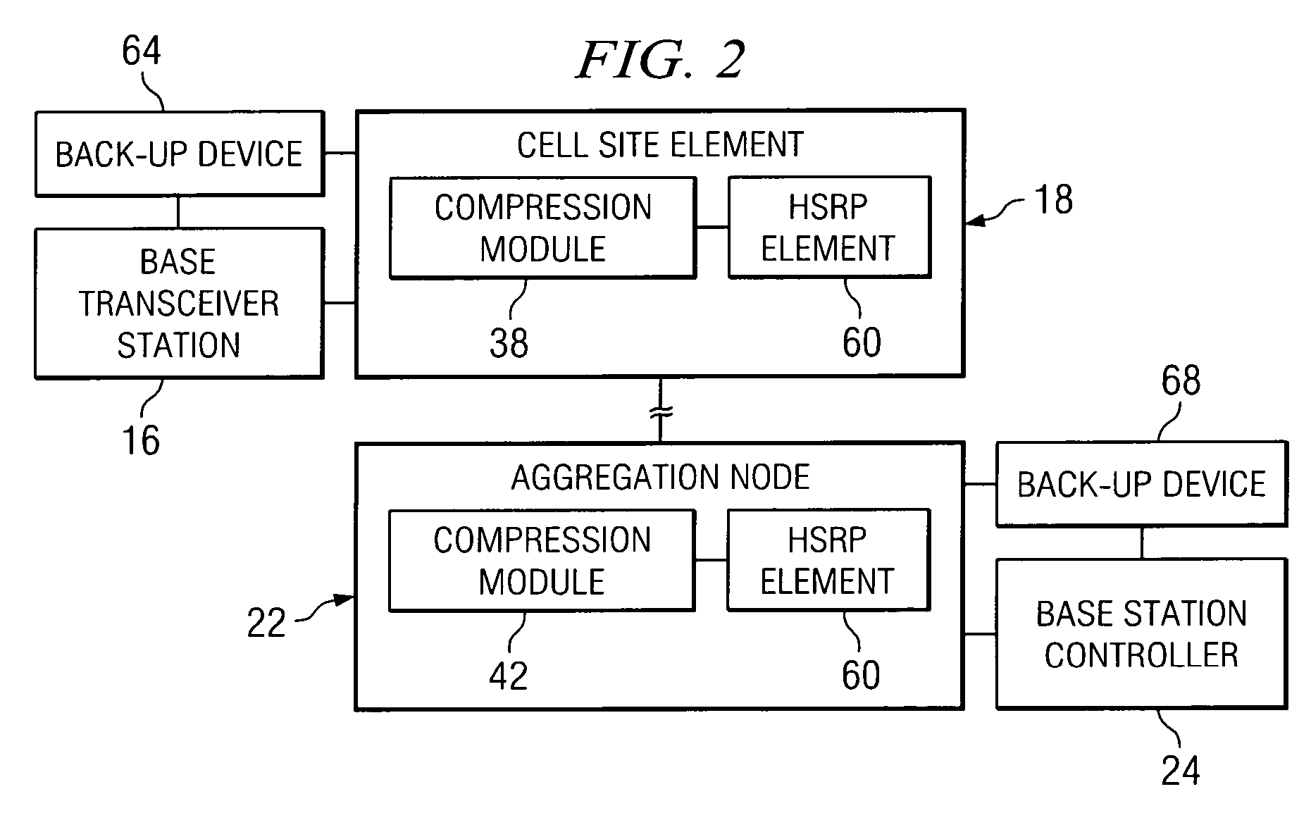
[0005] From the foregoing, it may be appreciated by those skilled in the art that a need has arisen for an improved compression approach that addresses failover scenarios in a communications environment. In accordance with one embodiment of the present invention, a system and a method for synchronizing a back-up device are provided that substantially eliminate or greatly reduce disadvantages and problems associated with conventional compression / suppression techniques.
[0008] Certain embodiments of the present invention may provide a number of technical advantages. For example, according to one embodiment of the present invention, a communications approach is provided that achieves minimum congestion during a failover. This is a result of the synchronization between a primary device and a back-up device in the architecture. More importantly, the present invention reduces the number of packets that are lost and / or calls that are dropped. This performance advantage is critical to efficiency on the backhaul. Hence, by using the system outlined by the present invention, active calls are effectively preserved in the case of failover.

Problems solved by technology

Many architectures for effectuating proper data exchanges can add significant overhead and cost in order to accommodate a large number of end-users or data streams.
For example, a large number of T1 / E1 lines may be used to accommodate heavy traffic, but such lines are generally expensive and, thus, usage of each one should be maximized (to the extent that it is possible) in order to achieve a system benefit per-unit of cost.
However, many of the existing compression / suppression protocols are problematic in the case of failover.
This overwhelms any device residing at these locations.
This flooding causes oversubscription of the communication link [e.g. a T1 link] and results in a substantial number of packets and / or calls being dropped.
Accordingly, the ability to provide a communications system that consumes few resources, optimizes bandwidth, and properly addresses failover scenarios presents a significant challenge for network operators, service providers, and system administrators.

Method used


Image

  • System and method for synchronizing a back-up device in a communications environment
  • System and method for synchronizing a back-up device in a communications environment
  • System and method for synchronizing a back-up device in a communications environment

Examples


Embodiment Construction

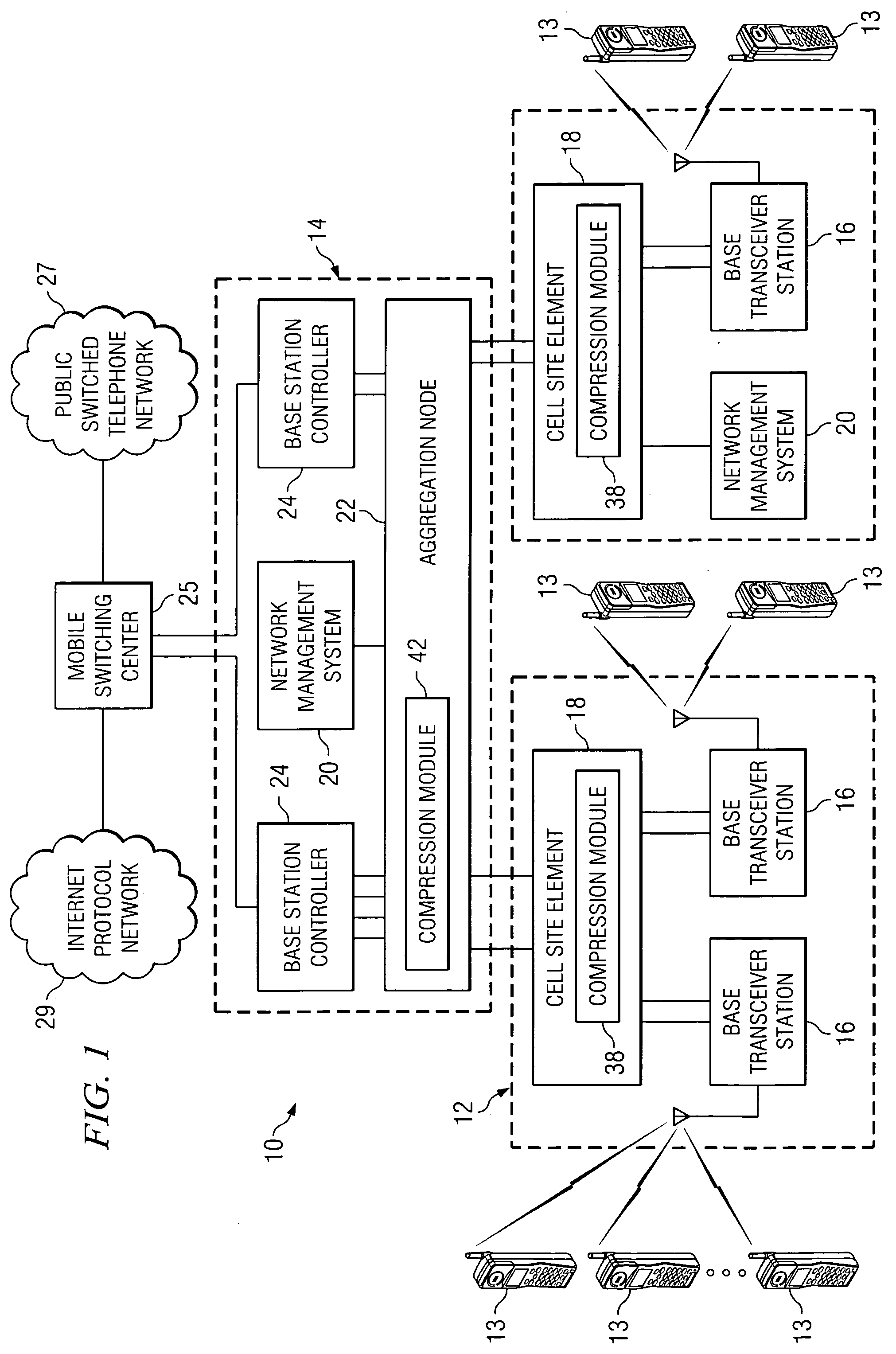
[0015]FIG. 1 is a simplified block diagram of a communication system 10 for compressing data in a communications environment. Communication system 10 may include a plurality of cell sites 12, a plurality of mobile stations 13, a central office site 14, a plurality of base transceiver stations 16, a plurality of cell site elements 18, and a network management system 20. Additionally, communication system 10 may include an aggregation node 22, a plurality of base station controllers 24, a mobile switching center 25, a public switched telephone network (PSTN) 27, and an Internet protocol (IP) network 29. Each cell site element 18 and aggregation node 22 may include a compression module 38 and 42 respectively.

[0016] Note the communications links extending between cell site element 18 and aggregation node 22, as compared to the number of communication links extending between cell site element 18 and base transceiver stations 16. This arrangement has been provided in order to illustrate ...


PUM


Abstract

An apparatus for communicating data is provided that includes a cell site element associated with a base transceiver station and comprising a compression module that is operable to receive a plurality of bits associated with a communications flow, to inspect the bits, to determine whether one or more samples included in the flow should be suppressed, and to compress the samples. The cell site element is coupled to a back-up device that is operable to assume responsibility for active flows in a case where a primary device fails. Data is exchanged between the primary device and the back-up device, the data guiding the back-up device in how to process the active flows.

Description

TECHNICAL FIELD OF THE INVENTION [0001] The present invention relates in general to the field of communications and, more particularly, to a system and a method for synchronizing a back-up device in a communications environment. BACKGROUND OF THE INVENTION [0002] Communication systems and architectures have become increasingly important in today's society. One aspect of communications relates to maximizing bandwidth and minimizing delays associated with data and information exchanges. Many architectures for effectuating proper data exchanges can add significant overhead and cost in order to accommodate a large number of end-users or data streams. For example, a large number of T1 / E1 lines may be used to accommodate heavy traffic, but such lines are generally expensive and, thus, usage of each one should be maximized (to the extent that it is possible) in order to achieve a system benefit per-unit of cost. [0003] Compression techniques can be used by network operators to produce high...

Claims


Application Information

Patent Timeline
IPC IPC(8): H04J3/14H04L12/56
CPCH04L45/00H04L45/586H04W28/08H04W40/02H04W92/12
Inventor KOREN, TMIMASONTI, JAGDISH V.ROBINSON, WALTER L.MITCHELL, NATHAN A.
Owner CISCO TECH INC
Learn More