
Method and apparatus for installing a helical pile

Inactive Publication Date: 2007-05-17
NIMENS JOSEPH R E
View PDF6 Cites 18 Cited by
  • Summary
  • Abstract
  • Description
  • Claims
  • Application Information

AI Technical Summary

Benefits of technology

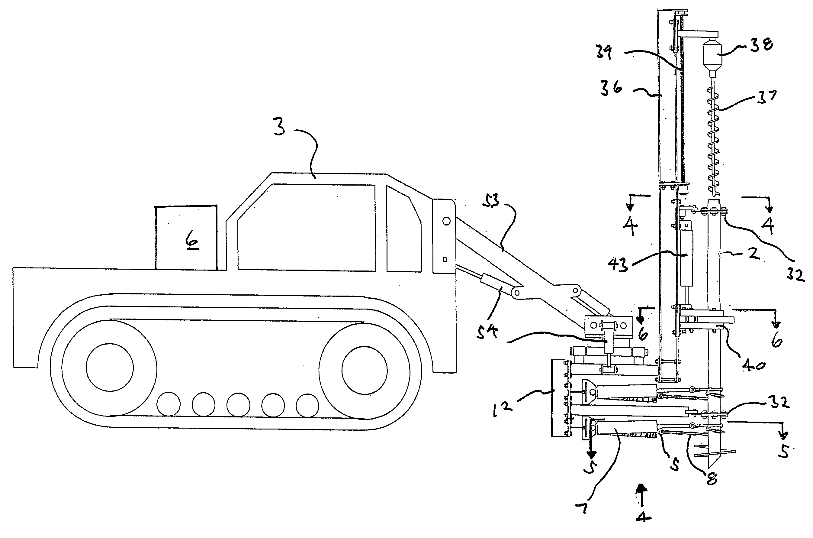
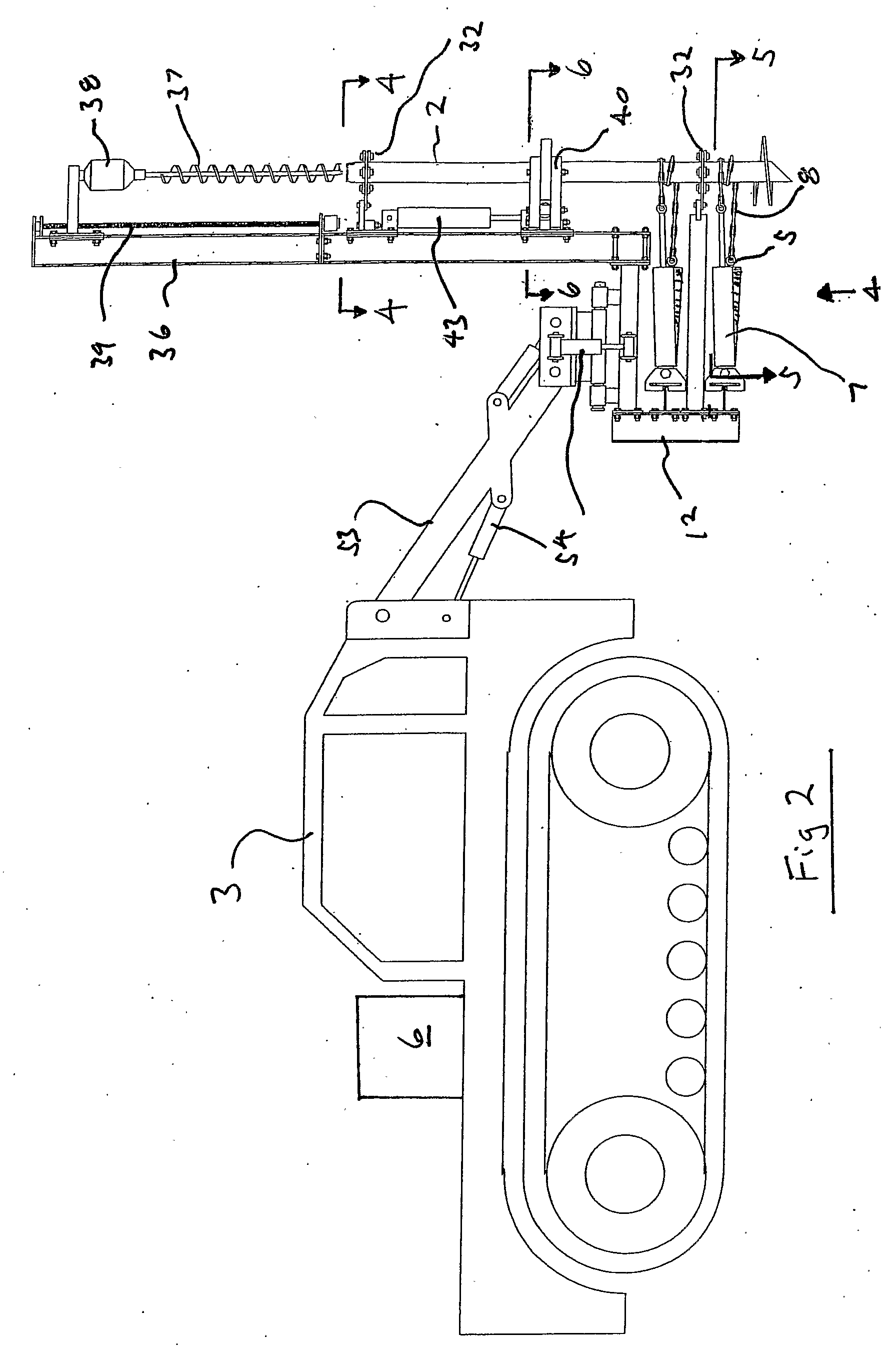
[0007] The invention therefore provides a method and an apparatus that may be used to install a helical or screw pile whereby the need for the use of a large boom truck is eliminated or minimized, as is the requirement for physically welding, bolting or pinning an intermediary drive member or torque coupling to the end of the pile in order to connect the pile to the motor of a drive head. The invention provides for a drive mechanism that imparts rotational movement to a pile without appreciable movement or displacement of the drive mechanism in a direction generally parallel to the longitudinal axis of the pile.

Problems solved by technology

Traditionally helical piles were used primarily in areas of weak or wet soil and their application was somewhat limited as their installation was difficult without mechanical assistance.
While such a structure is effective in transmitting rotational movement from the motor to the pile, it can also require a considerable amount of labour to put into operation on account of the need to weld, bolt, pin or otherwise secure the torque coupling to the end of the pile.
Where a large boom truck is used to drive a lengthy helical pile, difficulties can arise when trying to maintain the pile in a vertical orientation due to the length of the pile and the weight of the drive motor that is attached to its upper end.
The cost of utilizing a trunk having an extruded boom can be significant.
Large boom trucks also restrict the ability to work in confined areas.
Attaching, removing and subsequently re-attaching the drive member is both time consuming and costly.

Method used


Image

  • Method and apparatus for installing a helical pile
  • Method and apparatus for installing a helical pile
  • Method and apparatus for installing a helical pile

Examples


Embodiment Construction

[0034] The present invention may be embodied in a number of different forms. However, the specification and drawings that follow describe and disclose only some of the specific forms of the invention and are not intended to limit the scope of the invention as defined in the claims that follow herein.

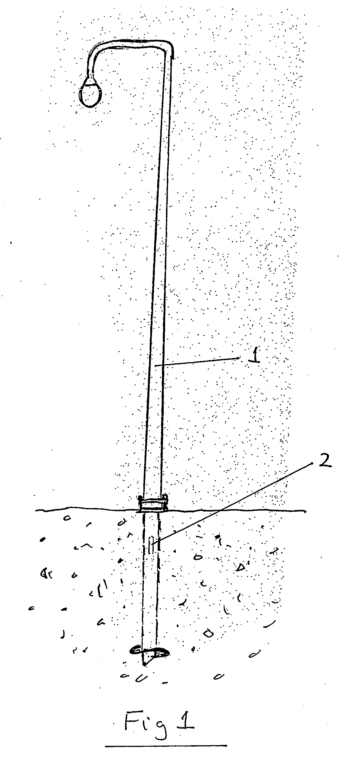
[0035] By way of introduction, FIG. 1 shows a typical street light standard 1 that is anchored to the ground through the use of a helical or screw pile 2. Most commonly helical pile 2 will be comprised of an elongate, generally hollow, cylindrical body or pipe having at its lower end a helical thread attached thereto such that rotation of the pipe causes the pile to be screwed or augered into the ground.

[0036]FIGS. 2 and 3 show a preferred embodiment of the present invention as it would typically be connected to a boom truck or vehicle 3. From a thorough understanding of the invention it will be understood that the apparatus constructed in accordance with the invention described herein...


PUM


Abstract

An apparatus and a method to assist in the installation of a helical pile. The apparatus comprises a drive mechanism having an engaged and a disengaged configuration. When in its engaged configuration the drive mechanism operatively grips the exterior surface of the helical pile. When in its disengaged configuration the drive mechanism operatively releases the exterior surface of the helical pile. Movement of the drive mechanism when in its engaged configuration causes rotational movement of the pile. When in its disengaged configuration the drive mechanism moves without rotation of the pile.

Description

FIELD OF THE INVENTION [0001] This invention relates to a method and an apparatus that may be used to install a helical or screw pile. BACKGROUND OF THE INVENTION [0002] Helical or screw piles have been used for decades to help support the foundation of buildings, bridges and other civil engineering structures. Traditionally helical piles were used primarily in areas of weak or wet soil and their application was somewhat limited as their installation was difficult without mechanical assistance. However, more recently helical piles have become considerably more widespread in use due to the advent of high torque motors that are used to rotate the piles and drive them into the ground. The resistence of a helical pile to both upward and carrying loads makes it attractive for use in a wide range of different situations. Today helical or screw piles are commonly used in foundation support for commercial and residential buildings, to help support temporary structures, as a support for stre...

Claims


Application Information

Patent Timeline
IPC IPC(8): E02D13/00E02D7/22E02D27/42
CPCE02D7/22E02D27/42
Inventor NIMENS, JOSEPH R.E.
Owner NIMENS JOSEPH R E
Learn More