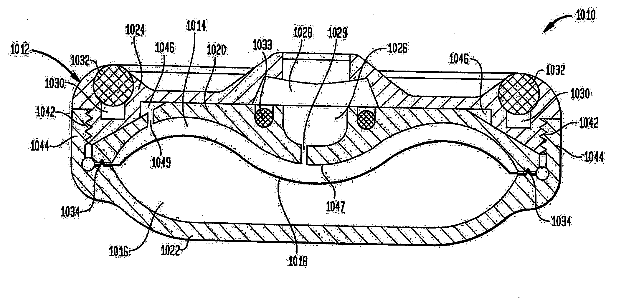
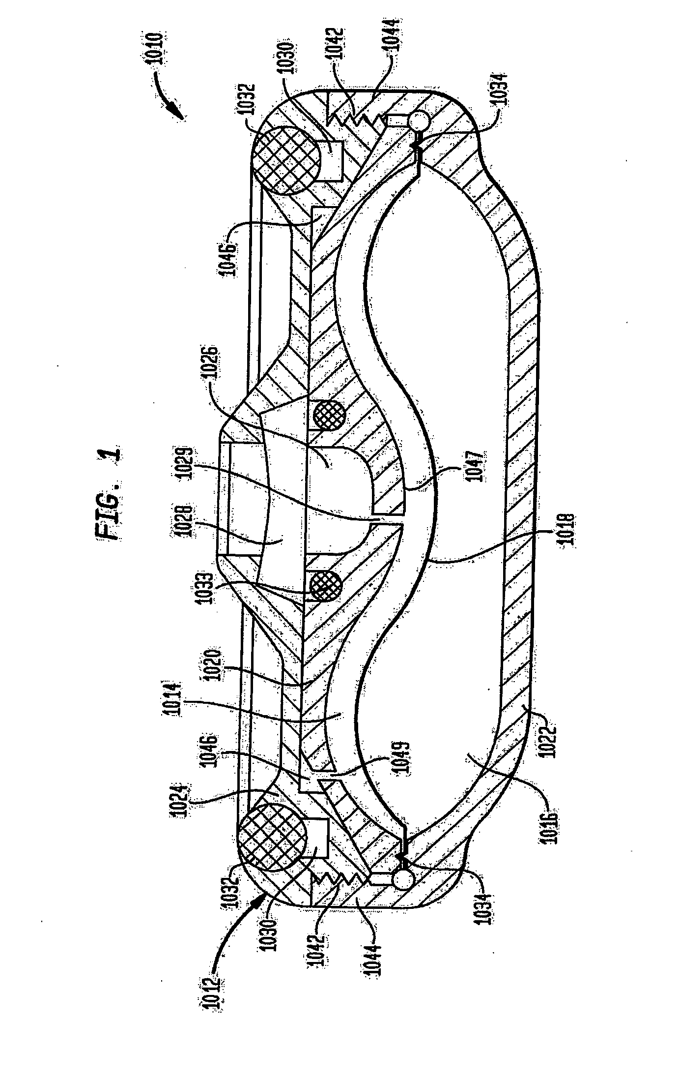
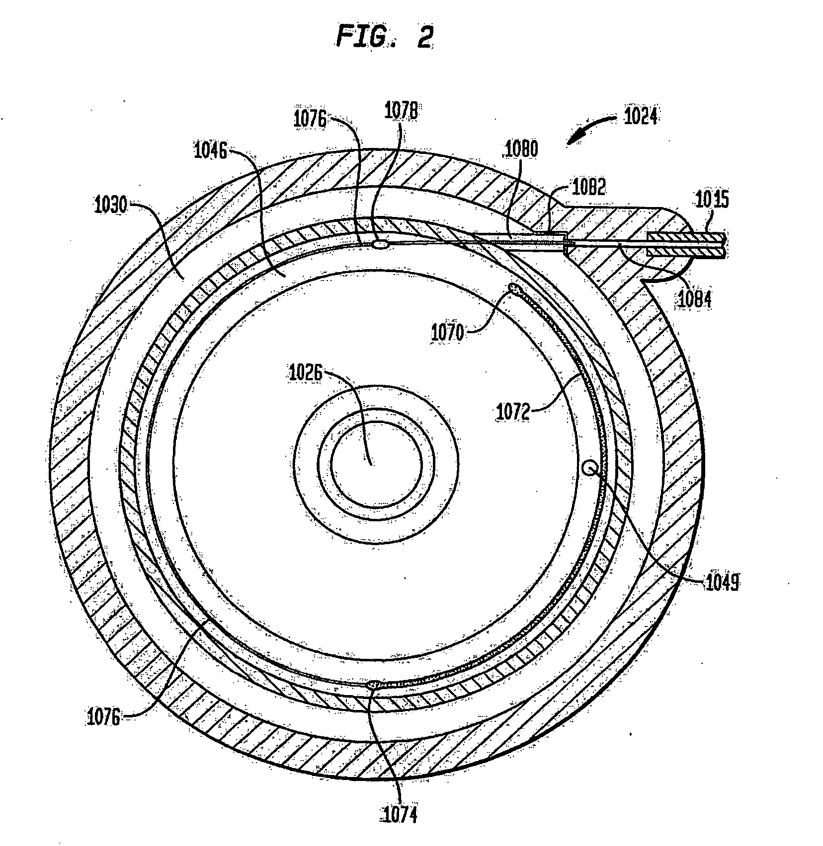
Variable flow infusion pump system

a variable-flow infusion pump and pump technology, which is applied in the field of implantable devices, can solve the problems of severe side effects, difficult administration of injections, and pain for patients of this type, and achieve the effects of reducing the size of the passageway, and reducing the flow rate of active substances

Inactive Publication Date: 2007-05-17
AQULINX MEDICAL
View PDF98 Cites 96 Cited by
  • Summary
  • Abstract
  • Description
  • Claims
  • Application Information

AI Technical Summary

Benefits of technology

[0018] In a fourth embodiment of this second aspect, the means for varying the flow rate of the active substance between the chamber and the outlet may include an elongate insert having a longitudinally varying cross section along its length. Movement of this elongate insert may increase or decrease the flow rate of the active substance.
[0019] A third aspect of the present invention includes an implantable device for dispensing an active substance to a patient including a housing defining a chamber, said housing having an outlet for delivering the active substance to a target site within the patient, the outlet in fluid communication with the chamber. The implantable device also includes a capillary in fluid communication between the chamber and the outlet, the capillary having an inner surface and a flow control element received within the capillary. The element has an outer surface opposing the inner surface of the capillary defining therebetween a passageway for the flow of the active substance therethrough. The outer surface of the element is preferably movable relative to the inner surface of the capillary to alter the flow of the active substance therethrough. The movement of the outer surface of the element may alter the shape and / or size of the passageway.

Problems solved by technology

Absent the use of an implantable pump or the like, a patient of this type would be subjected to one or more painful injections of such medication fluids.
In the case of pain associated with more remote areas of the body, such as the spine, these injections may be extremely difficult to administer and particularly painful for the patient.
Furthermore, attempting to treat conditions such as this through oral or intravascular administration of medication often requires higher doses of medication and may cause severe side effects.
Typically, such pumps require rather bulky outer housings, or casings, for accommodating the aforementioned medication and propellant chambers, and septa associated therewith.
Often times, implantable pumps are limited to rather small areas within the body.
Depending upon the size of the patient for which the pump is implanted, this limited area may be even further limited.
For example, a person having smaller body features, or those containing abnormal anatomy, may present a doctor implanting a constant flow pump with some added difficulty.
Further, patients may be uncomfortable having standard sized constant flow pumps implanted in them.
Such pumps are often times capable of being felt from the exterior of the patient.
However, both of these types of programmable pumps require intricate designs and complicated controlling mechanisms.
However, the benefit of providing a variable flow rate pump cannot be forgotten.
However, constant flow rate pumps typically may only provide such relief by allowing for direct injections of painkillers or the like through the aforementioned bolus port, which provides direct access to the affirmed area.
While indeed useful, this method amounts to nothing more than additional painful injections, something the pump is designed to circumvent.

Method used


Image

  • Variable flow infusion pump system
  • Variable flow infusion pump system
  • Variable flow infusion pump system

Examples


first embodiment

[0113]FIGS. 9, 10a and 10b show a first example of the first embodiment resistor 32, where elastic filament 52 is located concentrically in resistor capillary 54. This configuration forms a ring-shaped flow channel 56 through which fluid flows in a direction shown by arrow F. As is best shown in FIG. 10a, filament 52 includes a first end 58 attached to a stationary attachment 60, and a second end 62 attached to a movable attachment 64. Resistor 32 also has an effective length L extending between capillary entrance 66 to exit 68, and an initial diameter D1 (i.e.—2 times its radius R1). Additionally, capillary 54 has a diameter D3 (i.e.—2 times its radius R3). This will be similar throughout in the various other capillaries discussed herein.

[0114] In this example, movable attachment 64 is capable of moving in the opposite longitudinal directions shown by arrows A and B, while attachment 60 remains stationary. In operation, movement of attachment 64 in the direction of arrow B increase...

second embodiment

[0151] In operation of this second embodiment, fluid is introduced into hollow interior 304 in the direction indicated by arrow 314. Upon the sufficient build up of pressure created by the flow of the fluid, the closed end 312 design of second member 308 forces the fluid to move in the direction indicated by arrow 315 (best shown in FIG. 17) and through the flow channel defined by the threaded configuration of the two members 320, 308. The degree of overlap of the two threaded geometries determines the hydraulic resistance, and thus the flow rate of the fluid. Therefore, the high overlap shown in FIG. 16 would result in a lesser flow rate than that of the low overlap depicted in FIG. 17. Nevertheless, the fluid ultimately emerges from the resistor design as illustrated by arrows 316. It is envisioned that in other examples in accordance with this embodiment of the present invention the shapes of the two members may vary, as can the particular thread design employed.

[0152] In a third...


PUM


Abstract

An implantable infusion pump system is disclosed. The pump system preferably includes an implantable pump and a removable module. The module may provide for varying flow rates of fluid being dispensed from the pump or may provide for a constant flow rate of such fluid. In the case of varying flow rate capabilities, the module preferably includes one or more sensors to determine information relating to the flow rate, electronics for analyzing the flow rate information, and a mechanism for physically altering the flow rate. Methods of dispensing a medicament to a patient are also disclosed, as are variations of the pump system.

Description

CROSS REFERENCE TO RELATED APPLICATIONS [0001] This application is a continuation-in-part of U.S. application Ser. No. 11 / 125,586, filed on May 10, 2005, U.S. application Ser. No. 11 / 126,101, filed on May 10, 2005 and U.S. application Ser. No. 11 / 157,437, filed on Jun. 21, 2005, the disclosures of which are incorporated herein by reference.BACKGROUND OF THE INVENTION [0002] The present invention relates to implantable devices, and more particularly to reduced size implantable pumps and programmable implantable pumps allowing for variable flow rates in delivering medication or other fluid to a selected site in the human body. [0003] Implantable pumps have been well known and widely utilized for many years. Typically, pumps of this type are implanted into patients who require the delivery of active substances or medication fluids to specific areas of their body. For example, patients that are experiencing severe pain may require painkillers daily or multiple times per day. Absent the ...

Claims


Application Information

Patent Timeline
Patent Type & Authority Applications(United States)
IPC IPC(8): A61M31/00
CPCA61K9/0024A61M5/141A61M5/16813A61M5/14586A61M5/14276A61M25/00A61M31/00
Inventor STEINBACH, BERNDWALLMANN, FRANKLEDERER, KLAUS G.SAAR, DAVIDDAVID, SIDNEY
Owner AQULINX MEDICAL
Why Eureka
Try Eureka