
Lightweight LED lighting systems for permanent and semi-permanent mounting on elevated structures having integrated support and thermal transfer features

a technology of led lighting and integrated support, which is applied in the direction of lighting applications, lighting support devices, lighting and heating apparatus, etc., can solve the problems of difficult options, large amount of metal required to disperse and draw heat away from high-power led lamps, and low flow rate of led lighting systems. achieve the effect of increasing or decreasing the flow ra

Active Publication Date: 2021-01-28
HORIZON OILFIELD SOLUTIONS
View PDF0 Cites 1 Cited by
  • Summary
  • Abstract
  • Description
  • Claims
  • Application Information

AI Technical Summary

Benefits of technology

The patent text describes a LED lighting system that is structurally strong enough to support its components. It also has a suitable amount of thermal mass to effectively cool the LED lamps when they are in use. The system has cooling fins on the outer edge of each lamp housing to ensure even air flow. The technical effect of this design is a more efficient and effective LED lighting system.

Problems solved by technology

In the portable market, and in particular, the construction and energy industries, there are certain areas where LED lighting systems are not widespread due to various technical problems and / or limitations in certain applications.
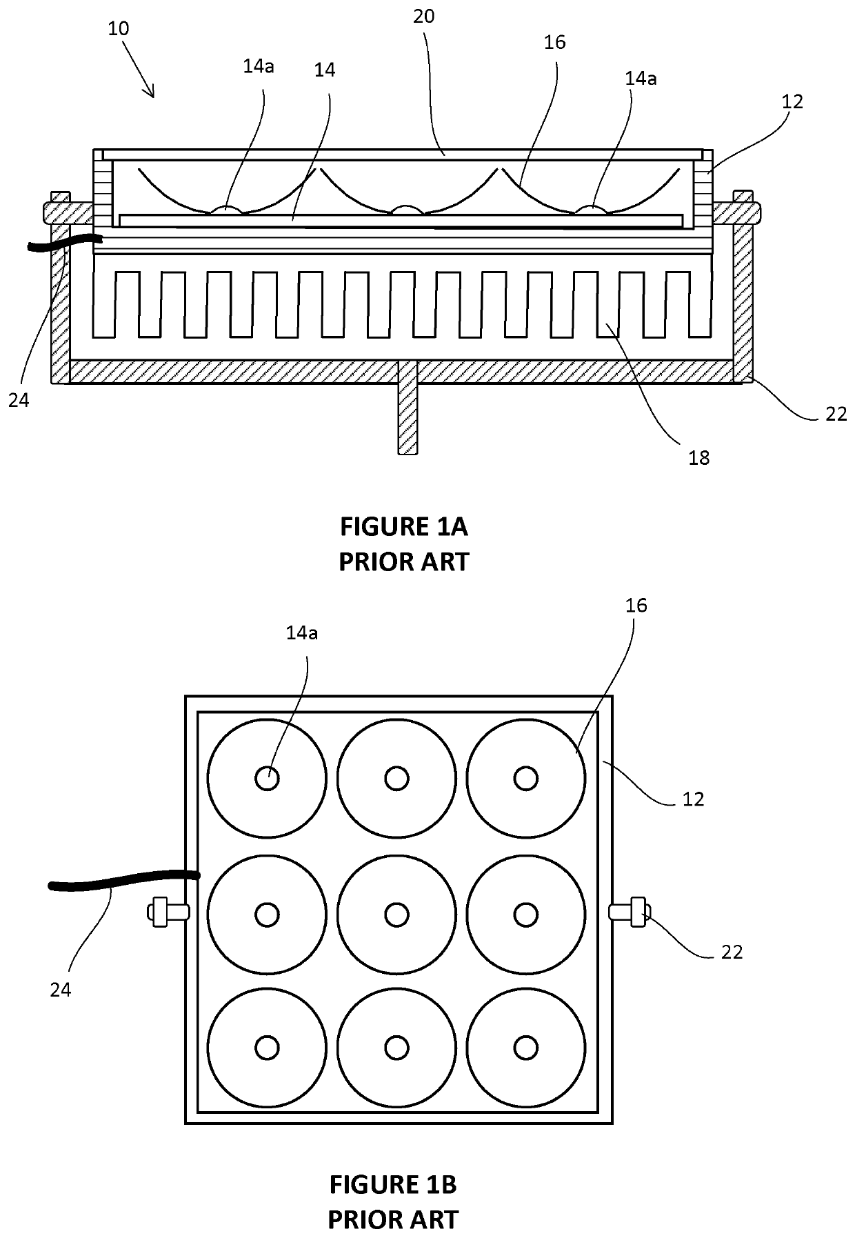
Although LED technology can supply lighting needs at a fraction of the energy consumption of metal halide technology, a drawback is the amount of metal required to dissipate and draw heat away from high-power LED lamps.
As such, in many cases the cost and weight of LED lighting systems can make them a challenging option for retrofit structures that were originally built for metal halide lighting systems and / or mounting LED lighting systems to structures that were not designed to support the weight of LED lighting systems.
As is known, drilling and service rigs and their masts are sophisticated and costly pieces of equipment designed for the complex task of drilling wells and servicing wells.
Importantly, while rigs are generally very well engineered structures, designed for their primary task of drilling or servicing wells, they must also be designed to be transported between well sites, and as such are often not designed to accommodate secondary tasks such as supporting lighting systems on their masts or crowns despite the desirability of having effective lighting at a central and high location of the site.
This can increase the costs of lighting the rig as both additional equipment and personnel may be required.
In addition, pieces of equipment such as fuel powered light towers are often not tall enough to provide a lighting source above the working surfaces of a rig.
For example, an LED lighting system mounted 165 feet (53 m) off the ground level where the workers need light, a 0.5 MM lumen LED system may not provide enough light on target; however, if that same 0.5 MM lumen system was added to an 80-foot (26 m) mast it would likely provide enough light on target.
Importantly, and as discussed below, a key drawback of LED lamps assemblies and LED lighting systems that mount to a rig crown or upper mast is the overall weight or weight to lumen ratio requirements of such systems to provide a specific light output.
Primarily, the problem of weight at the crown or upper mast of a rig is that during the process of raising and lowering the mast at a job site (after moving the rig between drilling locations), the extra weight of an LED lighting system acting at the end of the mast can subject the mast to enough force that the mast will bend and / or break and / or put additional stresses on lifting equipment.
As such, current prior art lighting systems that provide for example 1 MM-1.5 MM lumens can weigh in the range of 2,000-2,500 lbs and, as a result, are limited from being installed on many drilling rigs due to the stresses that such systems impose on a drilling rig as it is being raised and lowered.
While some rigs may be strong enough to allow this extra weight to be lifted, as noted above in some cases, it is the size and capabilities of the hydraulic ram lifting systems that limit the ability to use higher weight systems.
While larger hydraulic lifting systems may be utilized, this can also represent a significant additional cost to an operator.
Moreover, with the high weights of these systems, manpower and equipment is required.
In other words, the installation and removal of LED lighting systems requires the use and cost of a crane and loader for rigging in and rigging out, plus the extra time it takes to remove and reattach the LED lighting system after each move.
Since the rig companies often are compensated by their customer on time efficiency, this has created a barrier to market for many retrofit LED lighting systems and from gaining traction in the market.
While weight can be reduced by decreasing the lumen output of the system, lower lumen systems may not provide sufficient light.
While newer systems have been developed that continue to reduce the weight of lighting systems greater than 1.0 MM lumens to around 550 kg, there remain many rigs where this amount of added weight is still too high.
However, each of these components is generally heavy when assembled and when incorporated into an array of lamp assemblies can represent a significant weight.
As such, as the total weight of the LED lighting system includes the lamp assemblies as well as all the supporting frames, electrical cables, connectors, etc., the end result is that the desired ratios of grams / lumen as described above cannot be achieved with current designs.
Hence, for practical purposes, high power LEDs are rarely operated at temperatures higher than the recommended temperatures.
Further, there has been a need for LED lighting systems that reduce the effective net added weight and / or minimize the weight / lumen ratio when compared to prior art.
As such, the design of a lamp assembly should provide relatively precise light paths that illuminate the desired areas but do not allow excessive light to escape.
However, as light towers become taller, the precision of these boundaries becomes lower for a given reflector.

Method used


Image

  • Lightweight LED lighting systems for permanent and semi-permanent mounting on elevated structures having integrated support and thermal transfer features
  • Lightweight LED lighting systems for permanent and semi-permanent mounting on elevated structures having integrated support and thermal transfer features
  • Lightweight LED lighting systems for permanent and semi-permanent mounting on elevated structures having integrated support and thermal transfer features

Examples


Embodiment Construction

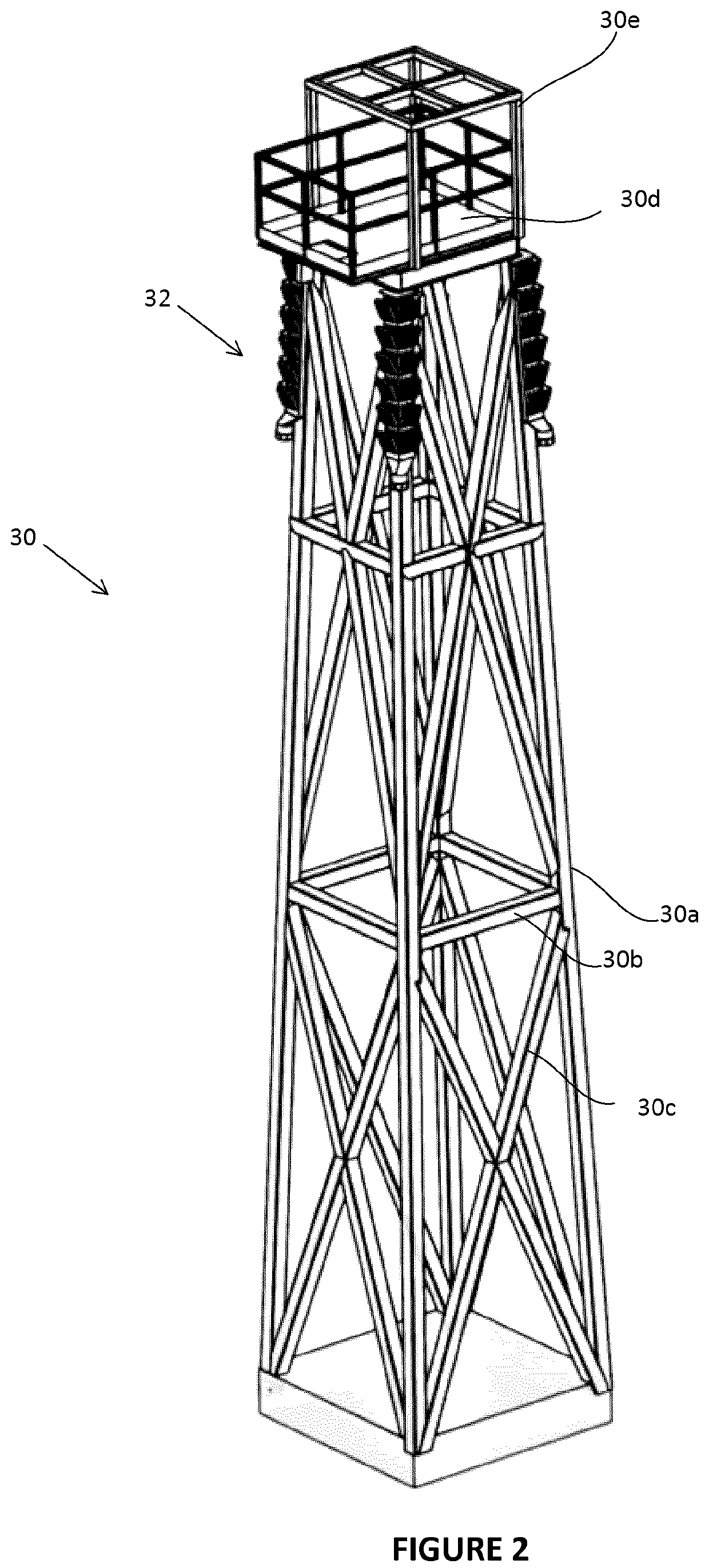
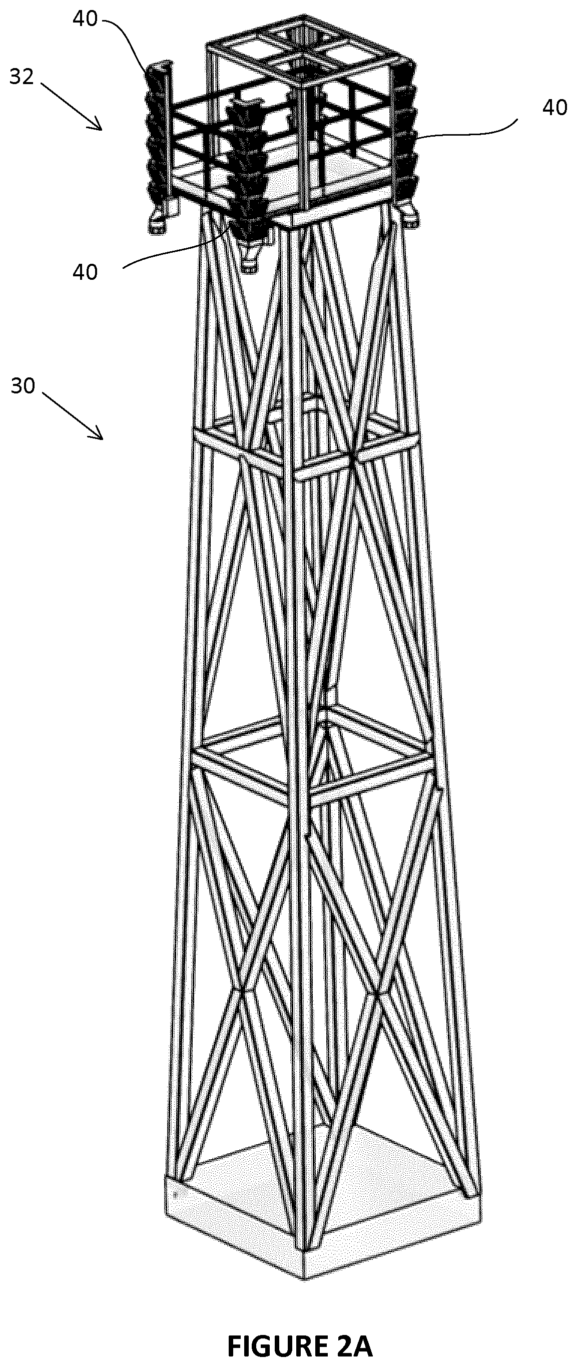
[0069]With reference to the Figures, LED lamp assemblies and LED lighting systems are described that combine structural and heat dissipation properties in combined systems that significantly reduces the weight of LED lamp assemblies and LED lighting systems.

[0070]Although many of the Figures illustrate and / or describe configuration to drilling rigs with higher lumen outputs, these are not meant to be limiting and it is understood that the systems described can be modified for configurations with applicability to smaller service rigs, other rigs of various heights, weights, geometry, etc. and are within the scope and spirit of the present invention. The systems described herein may also be integrated with other support systems. Various embodiments and aspects of the current invention are described that achieve one or more of the following:[0071]a. provide a desired level of lighting;[0072]b. reduce the overall net weight of an LED lighting system when compared to prior art systems;[0...


PUM

PropertyMeasurementUnit
heightsaaaaaaaaaa
weightaaaaaaaaaa
weightaaaaaaaaaa

Abstract

The invention relates to lightweight LED lighting systems for permanent and semi-permanent mounting on elevated structures, the lighting systems having integrated support and thermal transfer features. The systems are particularly suited for elevated mast systems and specifically for mast systems that are repeatedly lifted and lowered such as drilling and service rig masts. Specifically, the invention improves a) the weight / lumen ratios of LED lamp assemblies and LED lighting systems, b) the net added weight of LED lighting systems, c) the footprint of LED light systems and / or d) obviates the need for removing LED lighting systems or their sub-assemblies when transporting mast systems.

Description

FIELD OF THE INVENTION[0001]The invention relates to lightweight LED lighting systems for permanent and semi-permanent mounting on elevated structures, the lighting systems having integrated support and thermal transfer features. The systems are particularly suited for elevated mast systems and specifically for mast systems that are repeatedly lifted and lowered such as drilling and service rig masts. Specifically, the invention improves a) the weight / lumen ratios of LED lamp assemblies and LED lighting systems, b) the net added weight of LED lighting systems, c) the footprint of LED light systems and / or d) obviates the need for removing LED lighting systems or their sub-assemblies when transporting mast systems.BACKGROUND OF THE INVENTION[0002]LED lighting systems are well known and have a large number of applications. They are advantaged over past incandescent, fluorescent and metal halide systems in many applications for their energy consumption, robustness and durability.[0003]I...

Claims


Application Information

Patent Timeline
Patent Type & Authority Applications(United States)
IPC IPC(8): F21V29/61E21B15/00F21V29/67F21V29/89F21S8/04F21V21/30
CPCF21V29/61E21B15/00F21V29/67F21Y2115/10F21S8/043F21V21/30F21V29/89F21Y2105/16F21W2131/1005F21W2131/402F21V7/0083F21V29/673F21V29/76F21Y2105/10
Inventor CURLETT, JOSHUAWANLIN, HUGUES
Owner HORIZON OILFIELD SOLUTIONS
Learn More