
Vaporizing reactant liquids for chemical vapor deposition film processing

a technology of reactant liquid and film deposition, which is applied in chemical/physical processes, machines/engines, and combustion gas purification/modification, etc., can solve the problems of reducing the quality of films produced by these processes, difficult control, and processes that have difficulty producing the high reactant flow rate needed to achieve a high film deposition rate, and achieve accurate control. , the effect of increasing or decreasing the flow rate of the liquid

Inactive Publication Date: 2006-06-06
APPLIED MATERIALS INC
View PDF20 Cites 5 Cited by
  • Summary
  • Abstract
  • Description
  • Claims
  • Application Information

AI Technical Summary

Benefits of technology

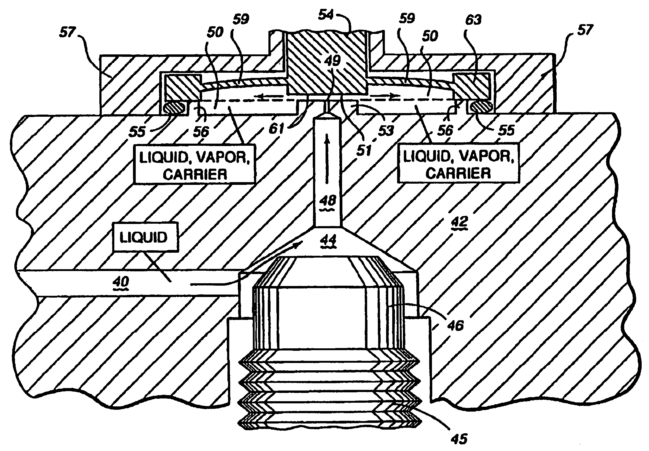
[0010]An advantage of the invention is that the vaporizer forms vapor by expansion in a pressure gradient, rather than evaporation by heating, and therefore can vaporize liquid at high flow rate such as those needed for some semiconductor fabrication processes.

Problems solved by technology

Thus, the amount of vapor transported is not an independent parameter and therefore is difficult to control.
As a result, CVD processes using a bubbler or boiler have not demonstrated the ability to consistently control the flow rate of the vaporized reactant, which decreases the quality of films produced by these processes.
An additional shortcoming of CVD processes using bubblers is that these processes have difficulty producing the high reactant flow rate needed to achieve a high film deposition rate.
However, the reliability of downstream hardware limits the use of a bubbler temperature above a certain value, and the adverse effect of excessive carrier gas flow rate on the quality of the deposited film limits the use of high carrier gas flow rates, thus limiting the amount of vapor that can be transported.
Thus, the amount of reactant vapor that can be transported is undesirably limited.
However, the vapor pressure of liquids commonly used in the deposition of semiconductor films (e.g., tetraethylorthosilane TEOS) is very small at normal operating temperatures; as a result, vapor transport limitations occur when a boiler is used in high pressure (e.g., atmospheric pressure) CVD processes.
Heating the boiler to the liquid boiling temperature could obviously improve the vapor transport for such processes, but the boiler temperature is limited by the reliability of the downstream hardware.
However, above a given limit, increases in liquid flow rate will result in only partial vaporization.
However, like the bubbler and boiler techniques, this technique relies on heated evaporation to vaporize the liquid, and thus can produce only limited vaporization rates.

Method used


Image

  • Vaporizing reactant liquids for chemical vapor deposition film processing
  • Vaporizing reactant liquids for chemical vapor deposition film processing
  • Vaporizing reactant liquids for chemical vapor deposition film processing

Examples


Embodiment Construction

)

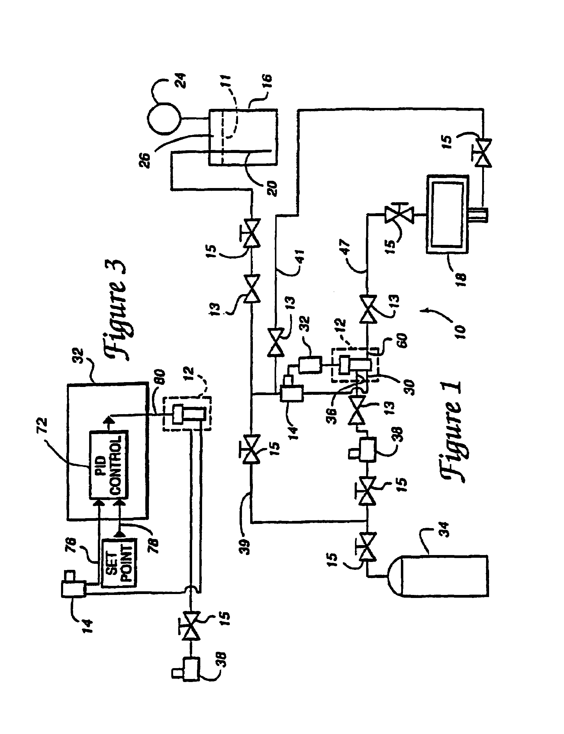
[0018]Turning now to the drawings, more particularly to FIG. 1, there is shown a liquid delivery system 10 which uses a specially designed vaporizer 12 for both liquid flow control and vaporization at a single stage. Liquid flow rate is controlled by a closed loop system between a liquid flow monitor 14 and the vaporizer. In the system 10, a liquid reactant 11, such as TEOS, trimethyl borate, tetraethyl borate, tetraethyl phosphate, tetraethyl phosphite, tetrakis(dimethylamino)titanium diethyl analog, water or the like is delivered from a liquid bulk delivery tank 16 to a CVD process chamber 18 of a conventional thermal or plasma-enhanced type. For example, such a chamber 18 is described in the following commonly owned issued U.S. Patents: U.S. Pat. No. 5,000,113, issued Mar. 19, 1991 to Adamik et al.; U.S. Pat. No. 4,668,365, issued May 26, 1987 to Foster et al.; U.S. Pat. No. 4,579,080, issued Apr. 1, 1986 to Benzing et al.; U.S. Pat. No. 4,496,609, issued Jan. 29, 1985 to Benzin...


PUM

PropertyMeasurementUnit
voltageaaaaaaaaaa
voltageaaaaaaaaaa
diameteraaaaaaaaaa

Abstract

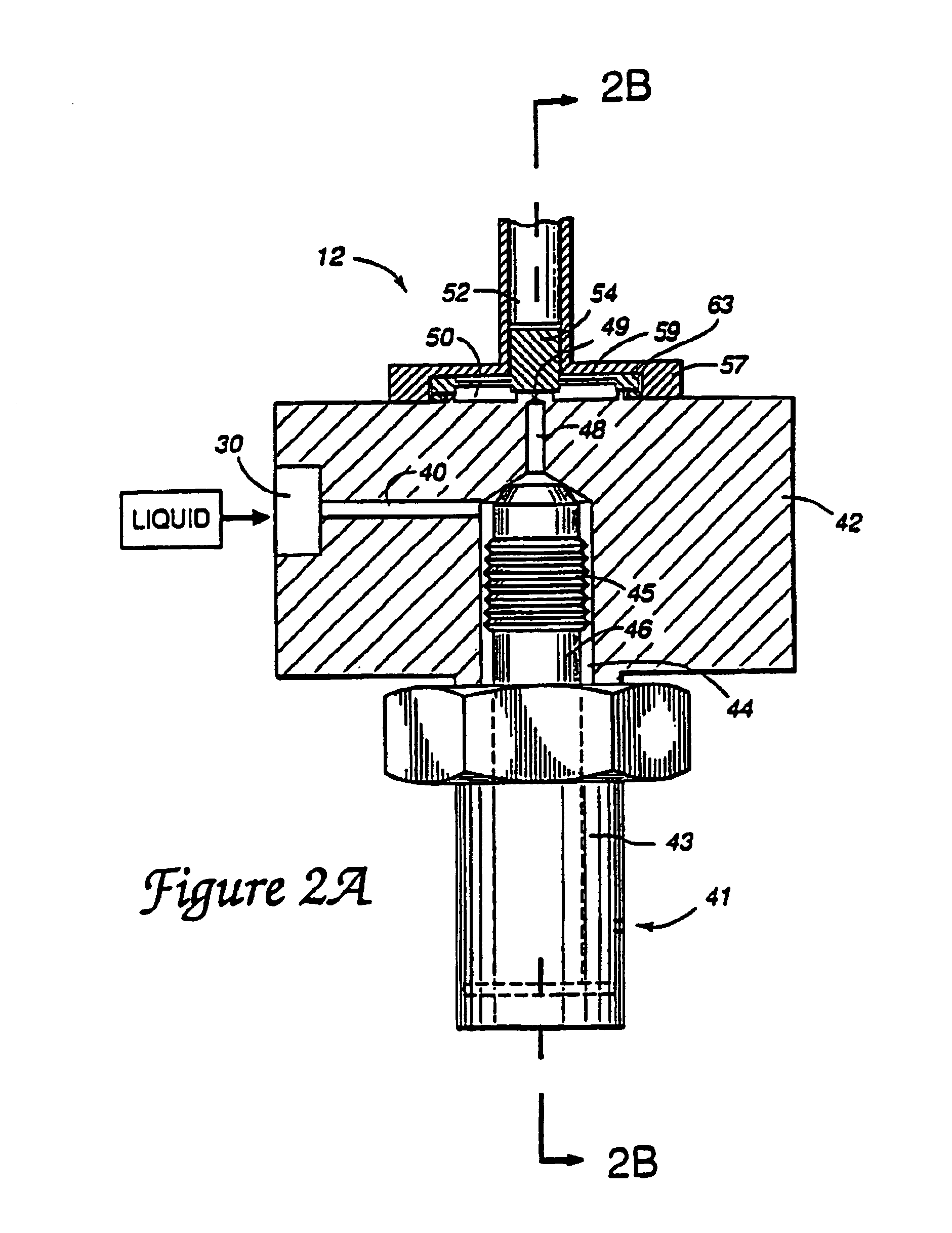
The disclosure relates to a vaporizer valve which accepts a carrier gas and a pressurized liquid and forms a mixture of the carrier gas and vaporized liquid. An internal cavity receives the carrier gas through a carrier aperture and the liquid through a liquid aperture, and the mixed gas and vapor are exhausted out of the cavity via a third aperture. A moveable diaphragm disposed adjacent to the liquid aperture forms a vaporization region having a pressure gradient. The liquid passing through this pressure gradient vaporizes due to expansion. By controlling the diaphragm position with a feedback control circuit responsive to a liquid flow rate monitor, the liquid flow rate may be controlled independently of the carrier gas flow rate.

Description

CROSS REFERENCE TO RELATED APPLICATIONS[0001]This application is a divisional of U.S. patent application Ser. No. 09 / 919,633, filed on Jul. 31, 2001, now U.S. Pat. No. 6,783,118, which is a continuation of U.S. patent application Ser. No. 09 / 660,208, filed on Sep. 12, 2000, now abandoned, which is a divisional of U.S. patent application Ser. No. 08 / 574,999, filed Dec. 19, 1995, now U.S. Pat. No. 6,224,681, which is a File Wrapper Continuation of application Ser. No. 08 / 278,984, filed Jul. 22, 1994, now abandoned, which is a File Wrapper Continuation of original application Ser. No. 07 / 990,755, filed Dec. 15, 1992, now abandoned, which are all incorporated by reference. This application is related to previously-filed U.S. patent application Ser. No. 07 / 912,024, filed Jul. 9, 1992, (now U.S. Pat. No. 5,419,924), which is a continuation of Ser. No. 07 / 626,274, now abandoned.BACKGROUND OF THE INVENTION[0002]The present invention relates generally to a device for vaporizing a liquid at a...

Claims


Application Information

Patent Timeline
Patent Type & Authority Patents(United States)
IPC IPC(8): B01F3/04B01J3/00B01D47/00B01F23/10C23C16/00C23C16/44C23C16/448C23C16/52H01L21/31
CPCB01F3/022C23C16/4481Y10S261/65B01F23/12
Inventor SIVARAMAKRISHNAN, VISWESWARENWHITE, JOHN M.
Owner APPLIED MATERIALS INC
Learn More