
Truss and purlin support apparatus and a method of making and using same with building supports and floor and roof sheathing

a technology of support apparatus and purlin, which is applied in the direction of load-supporting elements, structural elements, building components, etc., can solve the problems of prior art systems that included, costly in terms of material costs, and -channel joists

Inactive Publication Date: 2007-05-24
GREINER WALDEMAR H
View PDF0 Cites 22 Cited by
  • Summary
  • Abstract
  • Description
  • Claims
  • Application Information

AI Technical Summary

Benefits of technology

[0013] According to an aspect of one preferred embodiment of the invention, one or more of the central chord base portion and the chord side portions of each top chord and each bottom chord may preferably, but need not necessari

Problems solved by technology

Such prior art floor systems, especially insofar as they may have been constructed of LGS, may have been very time-consuming to construct and cumbersome to install, and often may have been quite costly in terms of material costs.
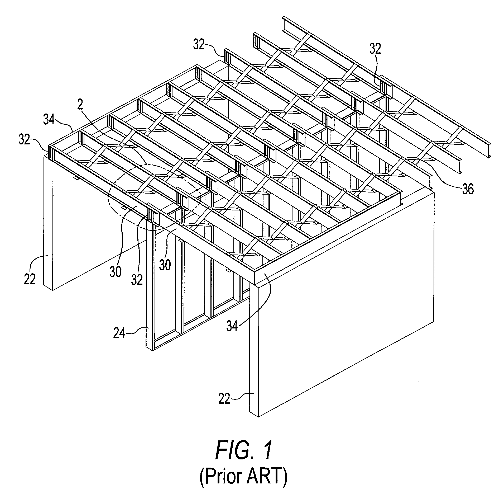
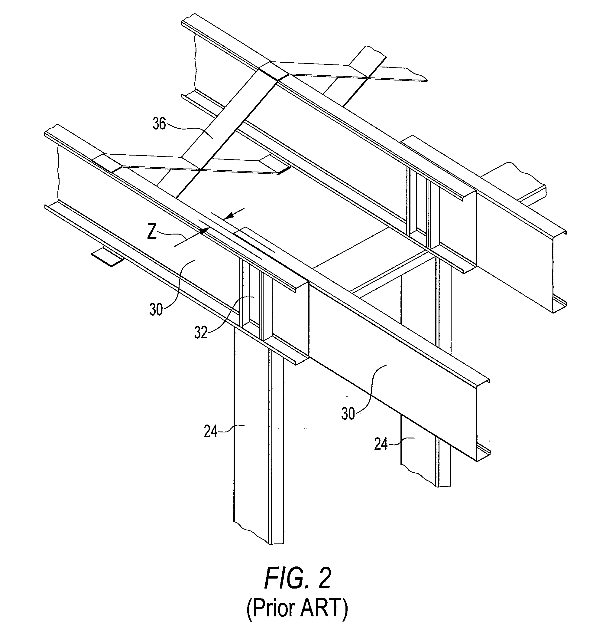
In addition, prior art systems that included “C”-channel joists 30 have been subject to the significant problem of providing the requisite level of stability for the “C”-channel joists 30 in their upright position (as shown in FIGS. 1 and 2).
The aforementioned problems of collapsing and / or over-turning under concentrated loads is one which may have been inherent in such prior art arrangements.
As such, in the prior art, it may have been necessary to install expensive “X”-bracing 36 within such prior art floor systems, which (apart from the significant added expense) may heretofore have been particularly difficult to accomplish for LGS constructions.
Floor sheathing that might heretofore have been placed on top of the offset prior art “C”-channel joists 30 often may not have been properly and / or readily aligned therewith.
In the result, considerable adjustments may have been necessitated during installation of sheathing over such prior art floor systems and may not have lended itself to a clean construction detail.
The aforementioned problem with prior art floor systems may have been somewhat more pronounced in low rise hotel constructions where a multitude of units, separated merely by center load bearing walls 24, may be present adjacent to one another.
In such situations, and / or if several floors are constructed on top of each other, prior art “C”-channel joists 30 may have become particularly unstable.
Moreover, such uses of prior art systems may not have afforded and / or guaranteed the desired level of sound stability, especially when under an applied load of several building stories.

Method used


Image

  • Truss and purlin support apparatus and a method of making and using same with building supports and floor and roof sheathing
  • Truss and purlin support apparatus and a method of making and using same with building supports and floor and roof sheathing
  • Truss and purlin support apparatus and a method of making and using same with building supports and floor and roof sheathing

Examples


Embodiment Construction

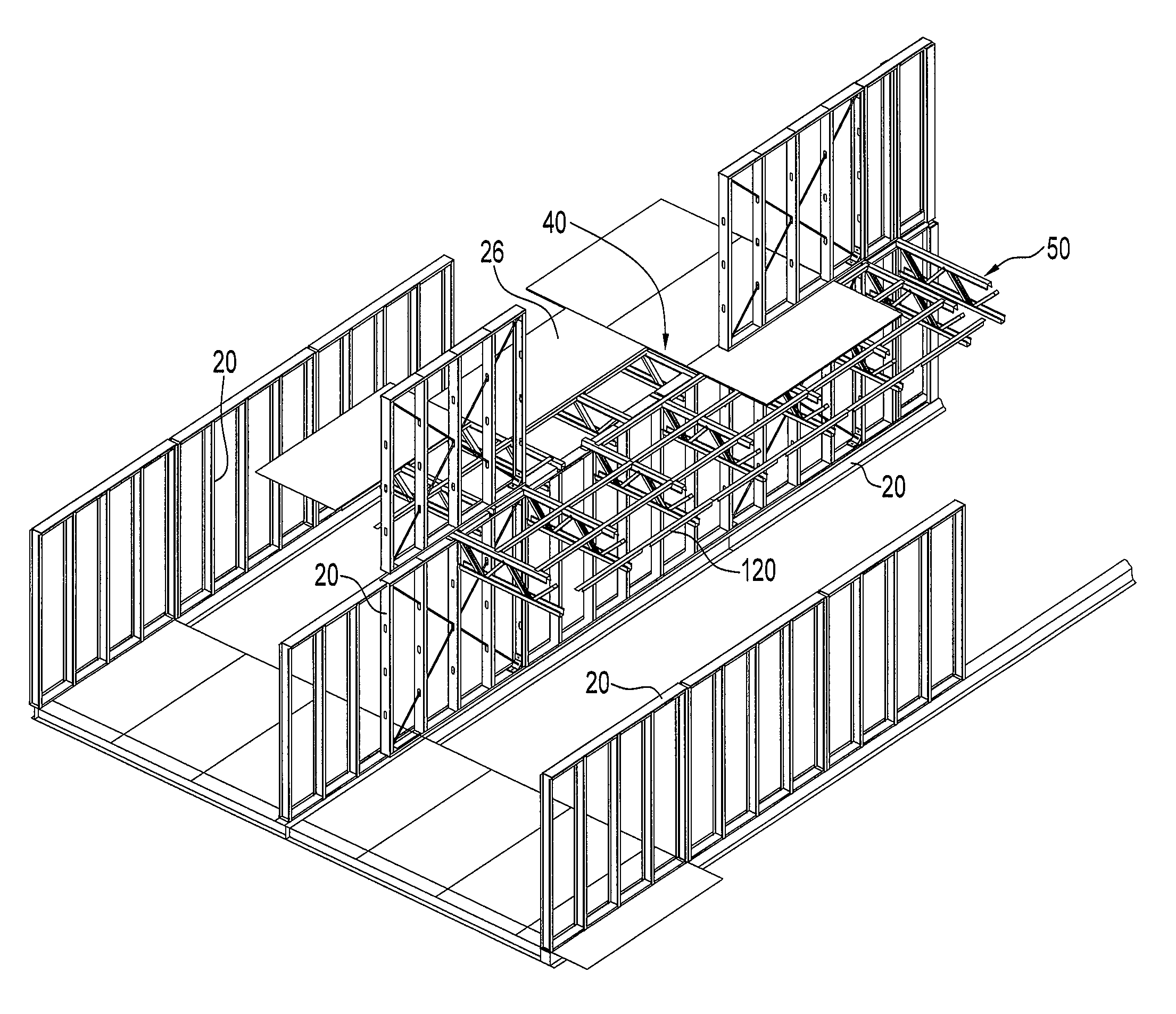
[0069] A truss and purlin support apparatus 40 according to the invention in shown in FIG. 3 of the drawings in use with building support members 20 and substantially planar substrate sheathing members 26. The apparatus 40 includes a plurality of Pratt-style elongate truss members 50 and a plurality of purlin members 120.

[0070] Each of the truss members 50 has at least two support portions 52 longitudinally spaced from one another. The support portions 52 are adapted to operatively engage and transfer loads to the building support members 20.

[0071] Each of the truss members 50 includes an elongate top chord 54b, an elongate bottom chord 54a, and a plurality of web members 80 securely extending between the top chord 54b and the bottom chord 54a. The top chord 54b, the bottom chord 54a, the web members 80, and the purlin members 120 are preferably constructed from roll-formed light gauge steel material. Each top chord 54b and each bottom chord 54a may preferably, but need not necess...


PUM


Abstract

A support apparatus is for use with building supports and floor or roof sheathing. The apparatus includes purlins and Pratt-style trusses. Each truss is supported on the building supports. Each truss includes top and bottom chords, and web members extending therebetween. Each purlin extends transversely of the trusses and has notches spaced along an underside thereof. Each notch is saddled over a top chord of one of the trusses, so as to restrict sliding movement of the purlins. The purlins support the floor or roof sheathing thereon. The top chord, the bottom chord, the web members, and the purlin members are constructed from roll-formed light gauge steel material.

Description

FIELD OF THE INVENTION [0001] The present invention relates to the field of floor and roof support apparatus and, more particularly, to a truss and purlin support apparatus and a method of making and using same with building supports and floor and roof sheathing. BACKGROUND OF THE INVENTION [0002] In the construction industry for buildings, including residential, commercial and institutional and high rise, there is a continuing need to achieve higher economic efficiencies in cost of materials, of fabrication, and of installation labor for floor and roof systems, as well as to achieve improved floor and roof structural efficiency. Though still largely undeveloped, the construction industry may be beginning to consider the use of light gauge steel (hereinafter, alternately referred to as “LGS” and / or “light weight steel”) constructions in this regard. [0003] In the prior art, conventional floor constructions in LGS may heretofore have used “C”-channel floor joists 30, such as those as...

Claims


Application Information

Patent Timeline
IPC IPC(8): E04C3/02
CPCE04B1/24E04B5/10E04B7/022E04B2001/2448E04B2001/2457E04B2001/2484E04B2001/249E04C3/09E04C3/11E04C2003/026
Inventor GREINER, WALDEMAR H.
Owner GREINER WALDEMAR H
Learn More