Roof panel clip

a technology for roof panels and clips, applied in the field of roof panels, can solve the problems of increasing the risk of damage, and increasing the loss of clips, so as to increase the uplift load capacity, increase the strength, and the effect of quick installation

Inactive Publication Date: 2005-06-14
MITCHELL JAMES
View PDF7 Cites 20 Cited by
  • Summary
  • Abstract
  • Description
  • Claims
  • Application Information

AI Technical Summary

Benefits of technology

[0025]It is an object of the present invention to provide a roofing clip that can be installed quickly.
[0026]It is an object of the present invention to provide a roofing clip that provides an increased up-lift load capability.
[0027]It is an object of the present invention to provide a roofing clip that provides strength to the roofing panels between purlins.
[0028]A continuous panel clip that extends typically ten feet in length rather than the usual prior art one to two inches, enabling the clip to span the distance between purlins and support roof panels over these distances. Shorter or longer lengths such as 12 inches to 20 feet or any length are possible for the continuous clip. The extended length of the continuous clip enables it to provide greater strength against uplift loads than that which was possible with the older short clips and this continuous clip can be installed more quickly than a series of the usual short clips commonly use to cover the same span.
[0029]The present invention includes a long “L” shaped bracket with attached individual, small clips spaced apart along the bracket at a uniform distance of typically 16 inches. The “L” bracket has two sections with one held parallel to the roof while the second section stands orthogonal to the first. The small clips are connected to the second section through slots placed in the second section. The slots allow for expansions and contraction of the roof under various environmental conditions as well under other loads placed on the roof. Attaching the long “L” shaped bracket securely holds all of the clips in place and insures that sufficient clips are present to properly secure the roof panels against up-lift loads.

Problems solved by technology

These clips that have a width of typically only 3 inches have worked reasonably well for years, but there are some problems that these clips present that have not previously been solved.
1. High spot up-lift loads can tear out a single clip. With the roofing panel being made less secure with one clip gone, the next clip is more easily torn out because it receives a greater load. The loss of clips continues until there is no support for the panel and it is blown away.
2. Roofing installers are often left to determine spacing between clips or even if a clip will be used in some locations. There is little in the prior art to force the installer to place clips at a preferred center to center spacing distance.
3. It is time consuming to install 15 individual clips along a 20 foot roofing panel. By installing all the clips, the roof's integrity is maintained, however, the cost is high because of the level of labor required to install the clips. If the spacing is decreased the cost goes down, but the integrity of the roof is compromised. These and other problems associated with prior art metal roof clips are addressed and solved by the present invention described in the following sections.

Method used


Image

  • Roof panel clip
  • Roof panel clip
  • Roof panel clip

Examples


Embodiment Construction

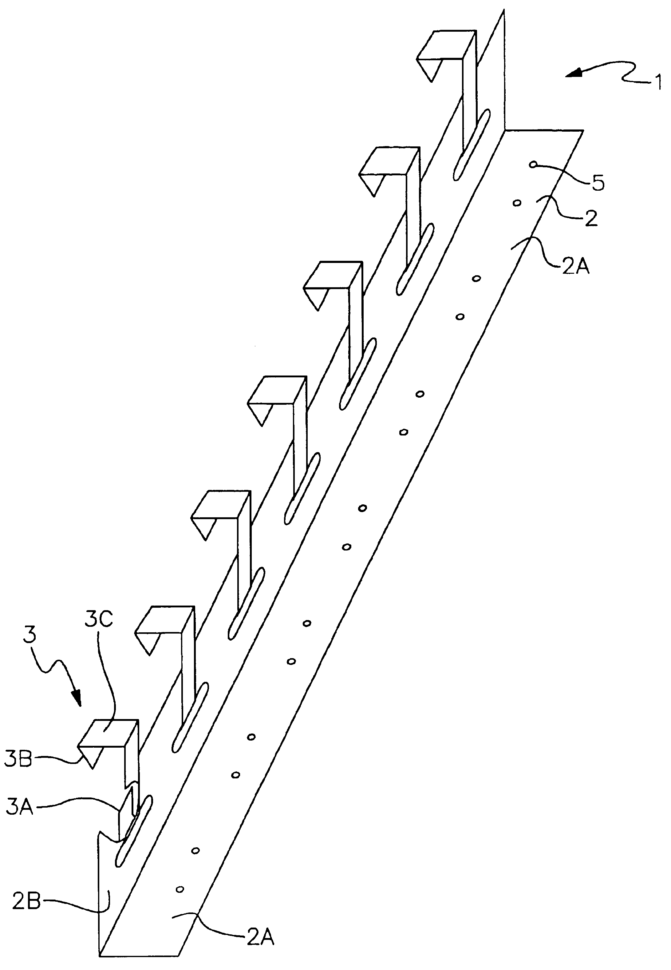
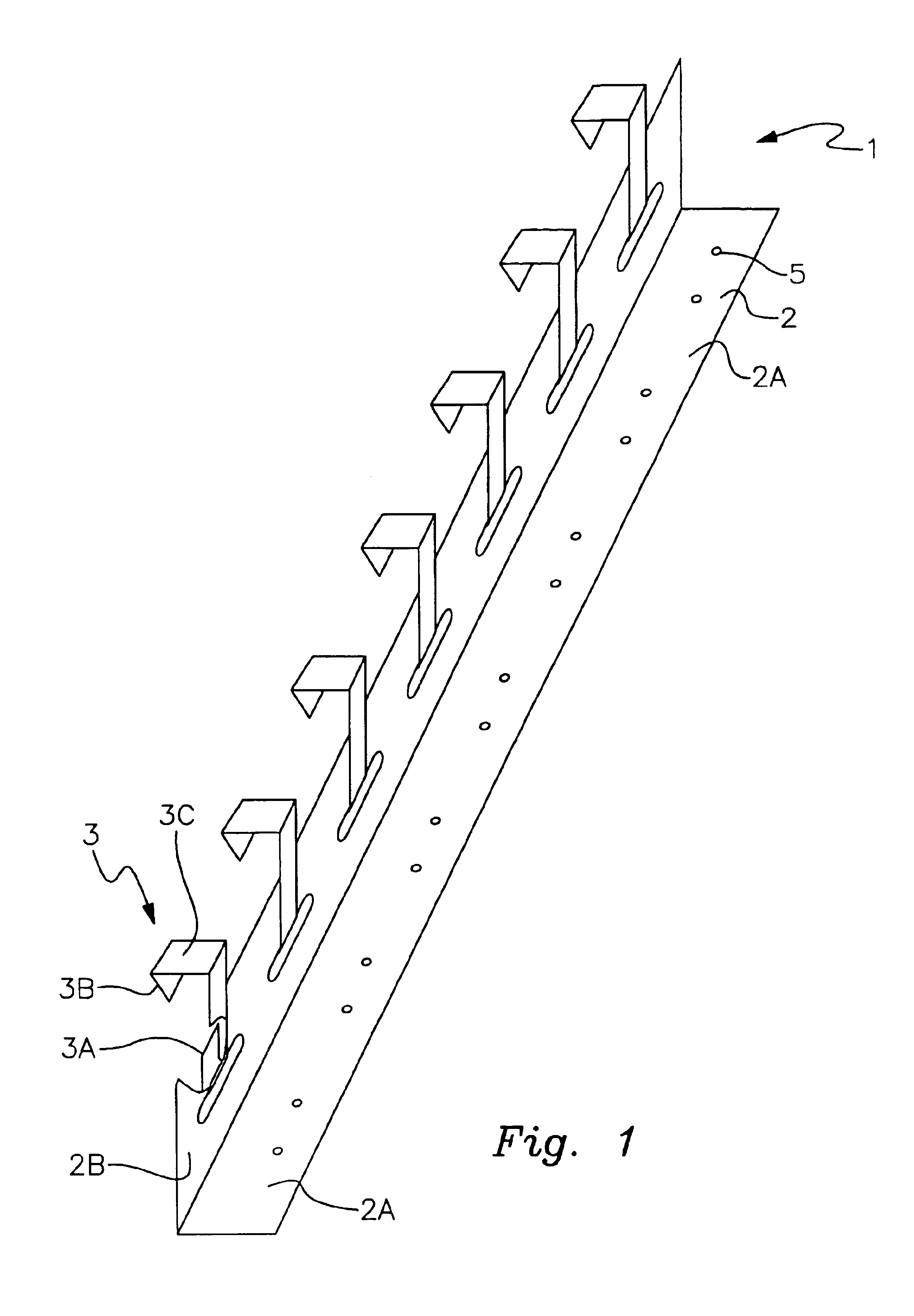
[0030]FIG. 1 is a perspective view of a first form of a continuous clip 1. This version of the continuous clip consists primarily of a long “L” bracket 2 which includes two sections, a mounting plate 2A and a clip support plate 2B, that is positioned orthogonally with respect to the mounting plate. The clip support plate includes a series of slots, such a slot 4 through which are installed a series of individual clips such as clip 3.

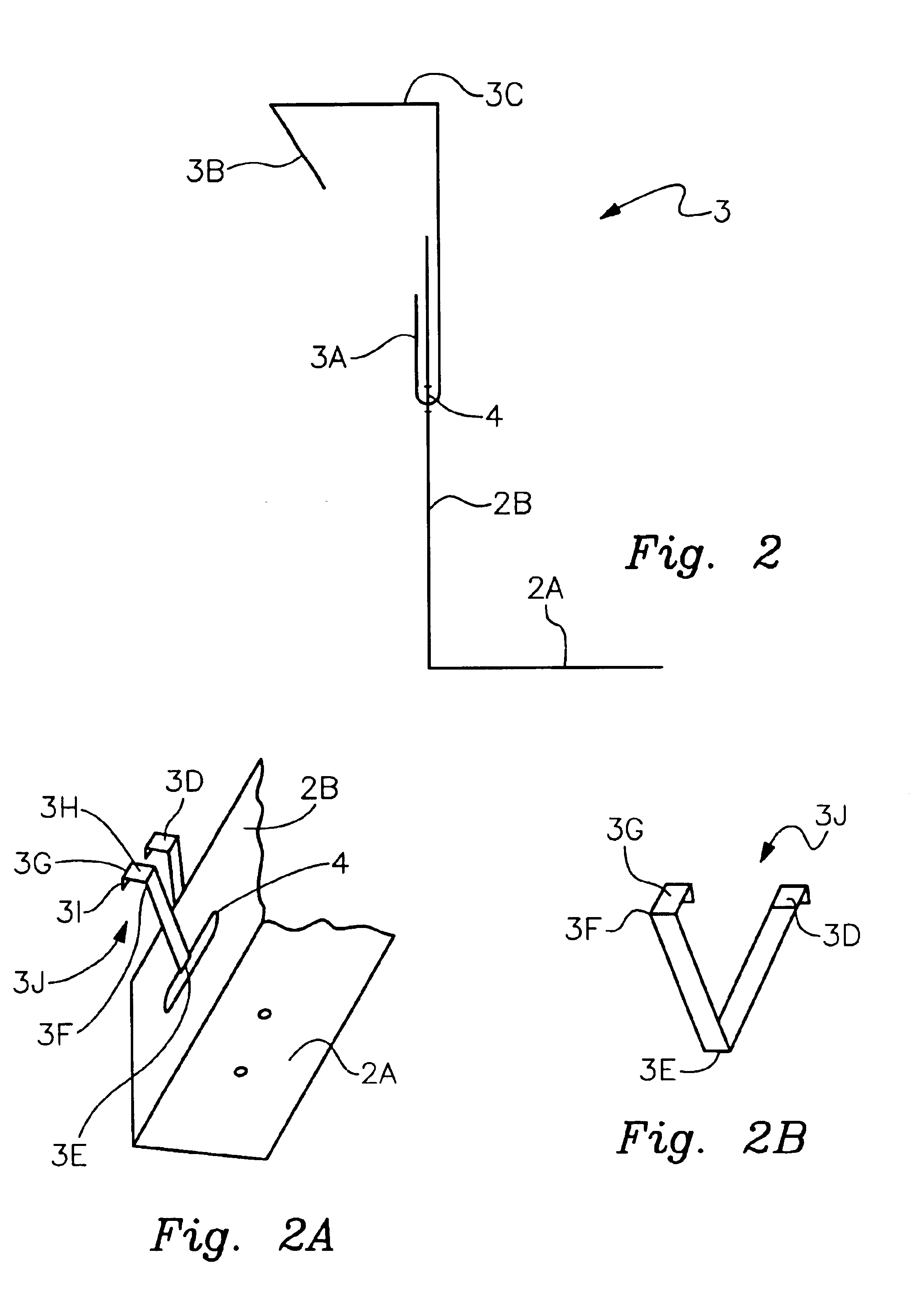
[0031]The first individual clip 3 located to the left in this figure and the clip support plate 2B are cut away to illustrate how an individual clip is bent up to provide a portion 3A of the individual clip that hold this clip in the slot 4. At the opposite end of the clip is a portion 3B that is positioned vertically. Connected to and located above the portion 3B is a portion 3C which is positioned horizontally. The portions 3B and 3C are used to connect the clip to the seams of the roofing panels as will be shown and described in connection with FIGS. ...


PUM


Abstract

A roof panel clip that extends ten feet in length rather than the usual prior art one to two inches, enabling the clip to span the distance between two purlins to support roof panels over these distances. The extended length of the clip enables it to provide greater strength against uplift loads than that which was possible with the older narrower clips and this continuous clip can be installed more quickly than a series of the ususal smaller clips used to cover the same span.

Description

[0001]This application claims the benefit of 60 / 349,619 filed Jan. 22, 2002.BACKGROUND[0002]1. Field[0003]The present invention relates to roofing clips and more particularly to such clips that are applied to secure metal roofing panels.[0004]2. Prior Art[0005]Typically, metal roofing panels are secured to roof using relatively small clips that are one to three inches long. Each clip is secured to the roof by means of several screws. The clips are positioned at regular intervals along a roofing panel at a spacing of 16 to 24 inches on center.[0006]A typical clip 14 is shown in FIGS. 8A and 8B and the use and method of installation is described in U.S. Pat. No. 4,796,403. These clips that have a width of typically only 3 inches have worked reasonably well for years, but there are some problems that these clips present that have not previously been solved.[0007]Among the problems are the following:[0008]1. High spot up-lift loads can tear out a single clip. With the roofing panel bein...

Claims


Application Information

Patent Timeline
Patent Type & Authority Patents(United States)
IPC IPC(8): E04D3/363E04D3/36E04D3/361
CPCE04D3/3602E04D3/363E04D2003/3615
Inventor MITCHELL, JAMES
Owner MITCHELL JAMES
Why Eureka
Try Eureka